8-72 Phaser 4500 Service Manual
5. Remove the six screws (five silver machine, 6; one gold machine, 6 mm) that
attach the Gear Assembly Housing to the frame.
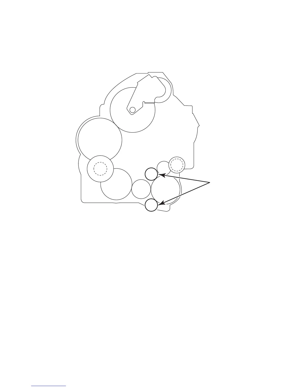
Note
The gears pointed out in this figure are not secured on their shafts and may
come off when you remove the Gear Assembly housing. Be careful not to
drop them.
6. Release the hooks of the Gear Assembly Housing, and remove it from the frame.
Replacement Notes:
■ When installing, engage the gears of the Gear Assembly Housing, Main
Motor, and Gear Assembly Plate by rotating Tray 1 and Tray 2 feeder
clutches while pressing inward on the Gear Assembly. Verify the plastic gear
housing is flush against the chassis sides before tightening screws. After
assembling, rotate the Main Motor by hand to check the engagement of the
gears.
■ Be sure that the gold 6 mm screw (called out as Screw A on the previous
page) is returned to its proper hole.
s4500-140
 Loading...


