60H5E11
Bracket unit
BRKT
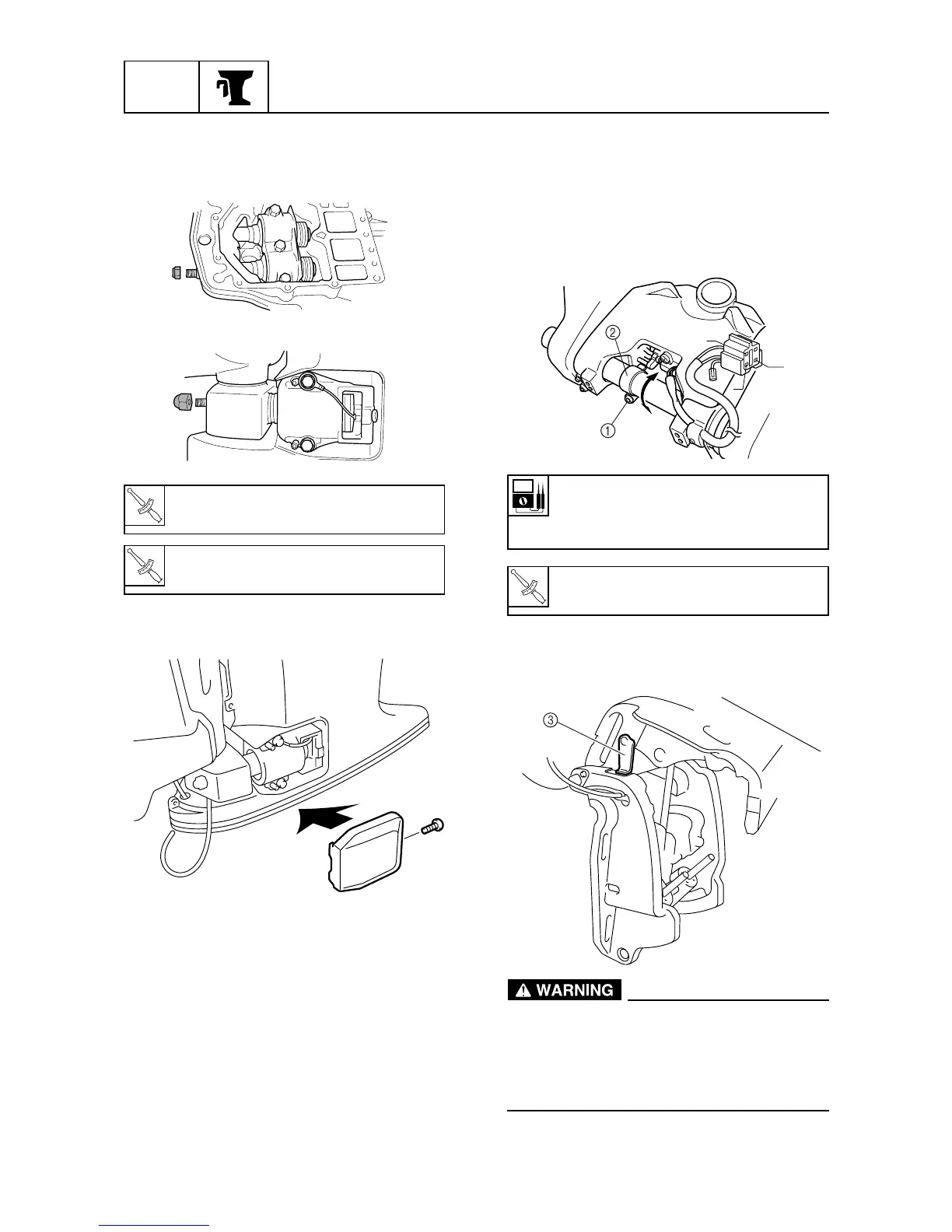
Trim sensor resistance:
Pink (P) - Black (B)
9-11 at 20°C (68°F)
Trim sensor cam screw 1:
2 N • m(0.2 kgf • m, 2 ft • lb)
T
R
.
.
Gy
P
B
7-47
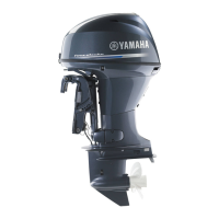
Install the upper case
1. Install the upper cace and tighten the up-
per mount and lower mount nuts.
60H71260
2. Install the lower mount cover.
60H71280
3. Connect the ground lead.
Adjusting the trim sensor cam
1. Fully retract the power trim and tilt unit.
2. Loosen the trim sensor cam screw 1.
3. Fix the trims sensor 2 cam where the speci-
fied trim sensor resistance is obtained.
60h71270
4. Fully tilt up the outboard motor, and lock it
with the tilt stop lever 3.
60h71290
After tilting up the outboard motor, be sure
to support it with the tilt stop lever. Other-
wise, the outboard motor could suddenly
lower if the power trim and tilt unit should
lose fluid pressure.
Upper mount nuts:
71 N • m (7.1 kgf • m, 52 ft • lb)
T
R
.
.
Lower mount nuts:
51 N • m (5.1 kgf • m, 38 ft • lb)
T
R
.
.