60H5E11
Electrical systems
ELEC
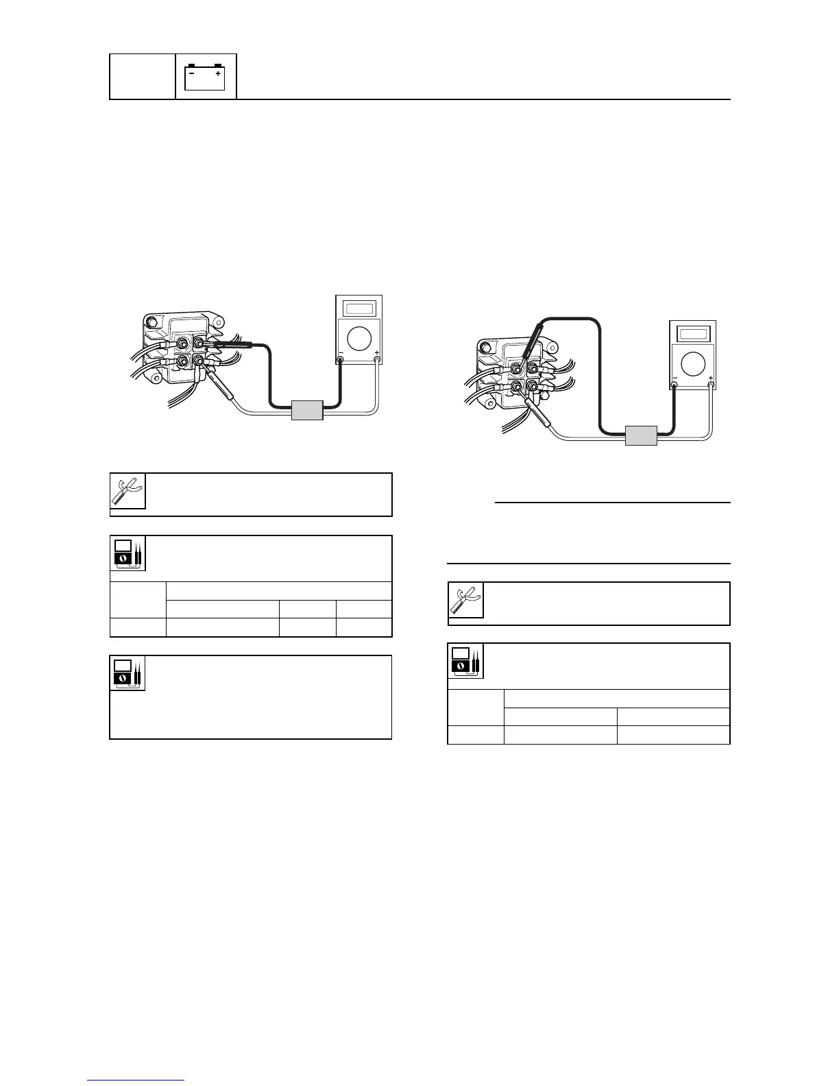
Checking the lighting coil
1. Remove the Rectifier Regulator cover, and
connect the digital circuit tester lead to the
lighting coil.
2. Measure the lighting coil output peak volt-
age. If the measurement is below specifi-
cation, check the lead and measure the
lighting coil resistance. Replace if neces-
sary.
60h80240
Checking the Rectifier Regulator
1. Remove the Rectifier Regulator cover, and
connect the digital circuit tester lead to the
Rectifier Regulator.
2. Measure the Rectifier Regulator output
peak voltage. Replace the Rectifier Regu-
lator, if the lighting coil output peak voltage
is on or above specification and the Recti-
fier Regulator output peak voltage is be-
low specification.
60h80250
NOTE:
Disconnect the output lead (Red(R)- Black(B))
of the Rectifier Regulator when measuring the
output peak voltage.
Lighting coil output peak voltage:
Green(G)- Green/white(G/W)
Lighting coil resistance
(use as reference):
Green(G) - Green/white (G/W)
0.20 - 0.30 Ω at 20°C (68°F)
Digital circuit tester : 90890-3174
Peak voltage adaptor B : 90890-03172
r/min
Unloaded
Cranking 1,500 3,500
DC V 3.0 20.0 50.0
Rectifier Regulator output peak voltage:
Red(R)- Black(B)
r/min
Unloaded
1,500 3,500
DC V 18 45
8-21
Digital circuit tester : 90890-03174
Peak voltage adapter B : 90890-03172



 To Next Page