60H5E11
7
2. Fully extend the power trim and tilt rods.
3. Remove the circlip 1 and manual valve 2.
Install the hydraulic pressure gauge 4 and
up-relief fitting 3.
60h70370
NOTE:
Quickly install the hydraulic pressure gauge
and up-relief fitting so that the fluid will not flow
out of the hole.
4. Tighten up the hydraulic pressure gauge
and up-relief fitting.
Reservoir cap:
0.7 N • m(0.07kgf • m, 0.5 ft • lb)
T
R
.
.
Recommended power trim and tilt
fluid:
ATF Dexron II
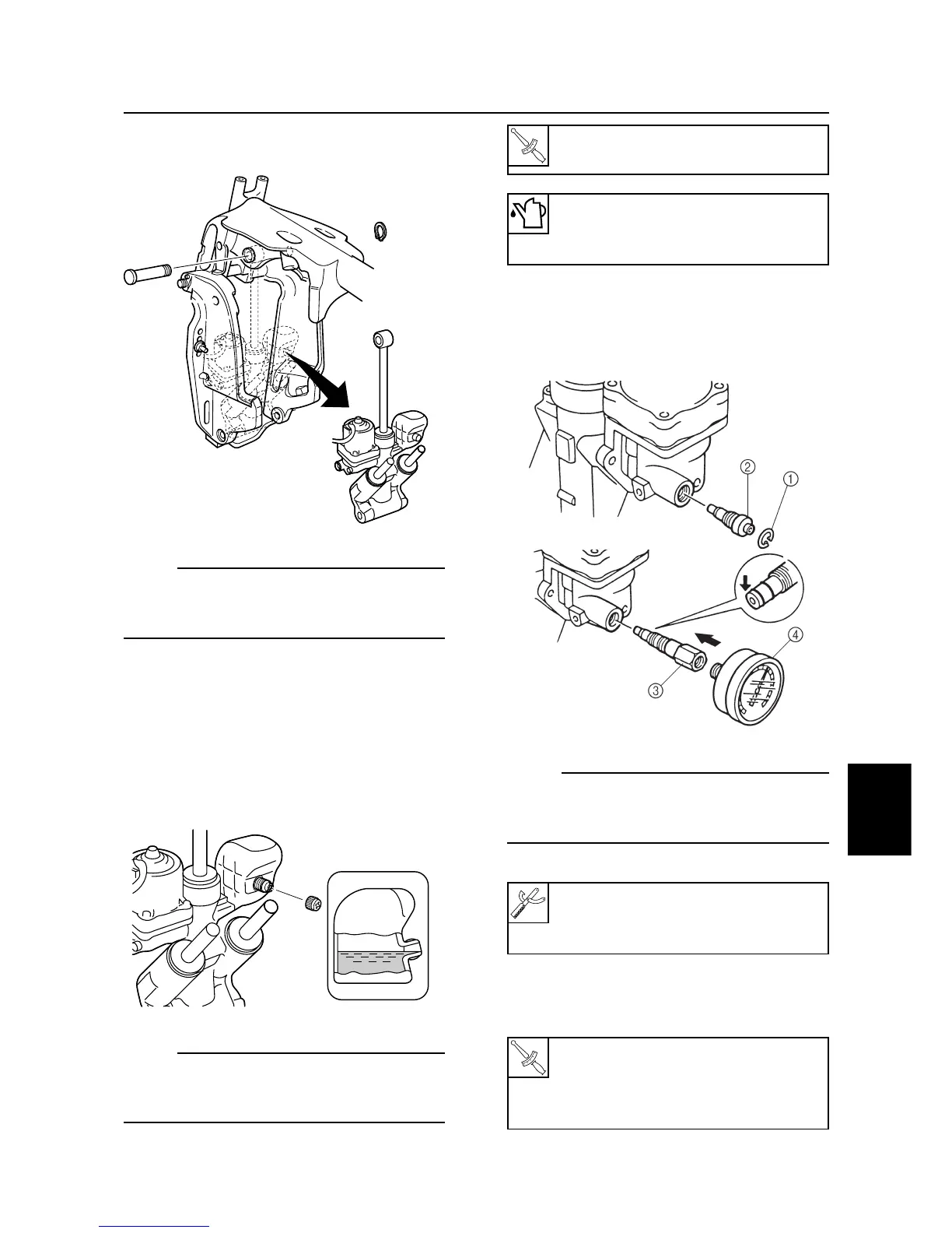
5. Remove the circlip, and pull out the upper
mount shaft.
60h70350
NOTE:
Pull out the upper mount pins downwardly at
an angle, while holding the power trim and tilt
unit with a hand.
6. Remove the collar.
Checking the hydraulic pressure of
the power trim and tilt unit
1. Check the fluid level. If it is lower than the
correct level, add sufficient fluid of the rec-
ommended type. Install the reservoir cap
after checking the fluid level.
60h70365
NOTE:
If the fluid is at the correct level, the fluid should
overflow out of the check hole when the cap is
removed.
Power trim and tilt unit
7-18
Hydraulic pressure gauge 4:
90890-06776
Up-relief fitting 3: 90890-06773
Hydraulic pressure gauge 4:
9 N • m (0.9 kgf • m, 6 ft • lb)
Up-relief fitting 3:
4 N • m (0.4 kgf • m, 3 ft • lb)
T
R
.
.



 To Next Page