60H5E11
8
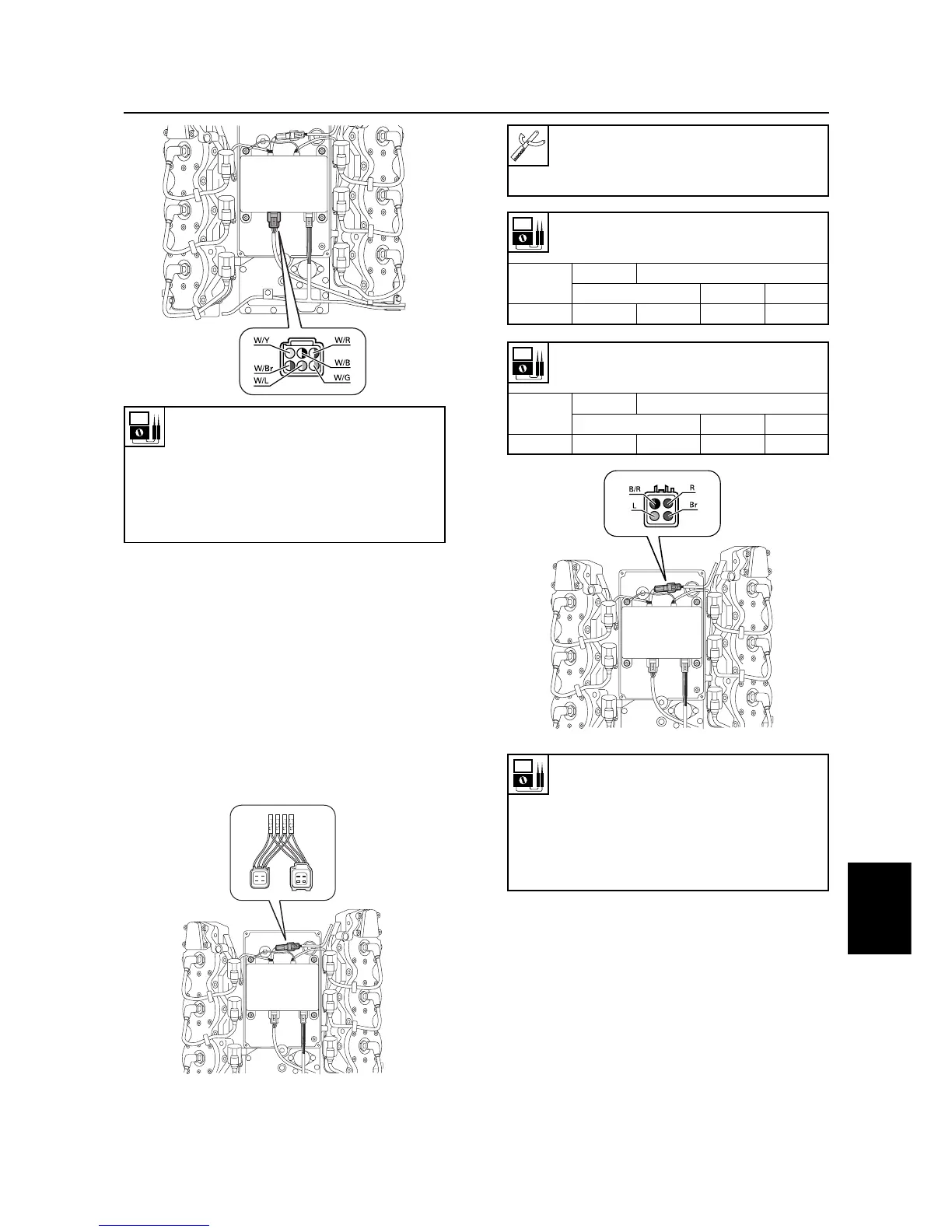
Pulser coil resistance (use as refer-
ence):
White/black(W/B)– White/blue(W/L)
White/brown(W/Br)– White/yellow(W/Y)
White/green(W/G)– White/red(W/R)
256 - 384 Ω at 20°C (68°F)
Digital circuit tester : 90890-03174
Peak voltage adapter B : 90890-03172
Test harness (FWY-4) : 90890-06771
Charge coil resistance
(use as reference):
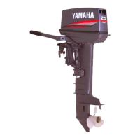
Bron(Br)– Red(R):
428 - 642 Ω at 20°C (68°F)
Blue(L) – Black/red (B/R)
64.4 - 96.6 Ω at 20°C (68°F)
Charge coil output peak voltage :
Brown(Br) – Red(R)
r/min
Unloaded
Loaded
Cranking 1,500 3,500
DC V 80 90 165 165
Charge coil peak voltage :
Blue(L) – Black/red(B/R)
r/min
Unloaded
Loaded
Cranking 1,500 3,500
DC V 30 30 160 165
8-12
Ignition system
Checking the charge coil
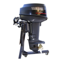
1. Remove the CDI unit cover.
2. Connect the charge coil and CDI unit with
the test harness (4 pins).
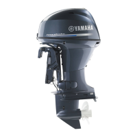
3. Measure the charge coil output peak volt-
age. If the measurement is below specifi-
cation, Check the leads, and measure the
charge coil resistance. Replace if neces-
sary.
60h80175
60h80170
60h80165