60H50280
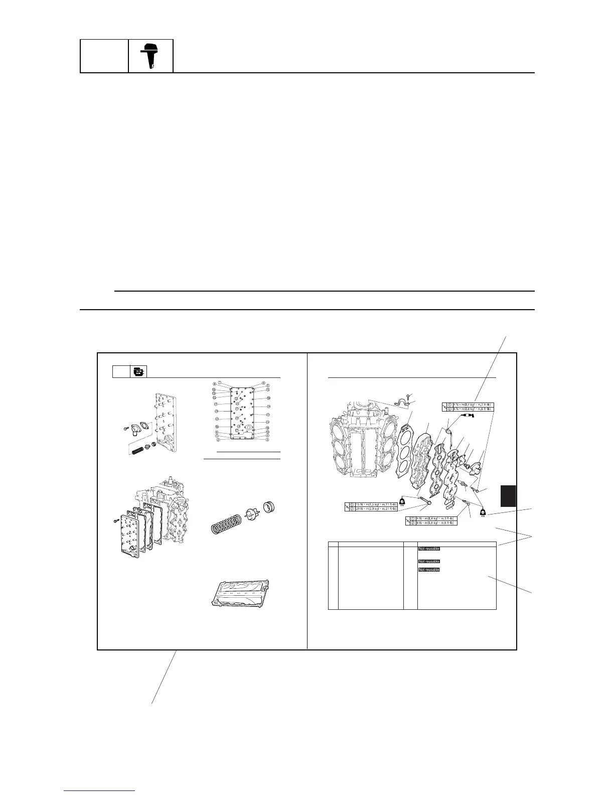
1 Gasket 2
2 Cylinder head 2
3 Thermo switch 2
4 Gasket 2
5 Cylinder head cover 2
6 Gasket 2
7 Thermostat 2
8 Thermostat cover 2
9 Bolt 8 M6 x 40 mm
10 Bolt 36 M6 x 30 mm
11 Bolt 24 M8 x 60 mm
12 Clamp 1
13 Bolt 2 M8 x 20 mm
14 Engine hanger 1
15 Spark plug 6
No. Part name Q’ty Remarks
Exhaust / Cylinder head
5-22
Cylinder head
60H5E11
Power unit
POWR
5-21
Removing the exhaust cover
1. Remove the pressure control valve.
60H50250
2. Remove the exhaust outer cover, and the
exhaust inner cover.
60H50260
60H50265
NOTE:
Loosen the bolts in the sequence shown.
3. Remove the cylinder block exhaust inner
cover.
4. Check the pressure control valve for cracks
or damage. Also check the pressure con-
trol valve seat for deformation. Replace
them if necessary.
60H50270
5. Check the spring for fatigue or deforma-
tion. Replace it if necessary.
6. Check the exhaust cover for distortion or
corrosion. Replace it if necessary.
60H50275
How to use this manual
Manual format
The format of this manual has been designed to make service procedures clear and easy to under-
stand. Use the information below as a guide for effective and quality service.
1 Parts are shown and detailed in an exploded diagram and are listed in the components list.
2 Tightening torque specifications are provided in the exploded diagrams and after a numbered step
with tightening instructions.
3 Symbols are used to indicate important aspects of a procedure, such as the grade of lubricant and
lubrication point.
4 The components list consist of parts and part quantities, as well as bolt, screw, O-ring, and hose
dimensions.
5 Service points regarding removal, checking, and installation are shown in individual illustrations to
explain the relevant procedure.
NOTE:
For troubleshooting procedures, see Chapter 9, “Troubleshooting.”
1-1
2
4
3
5
1