60H5E11
Power unit
POWR
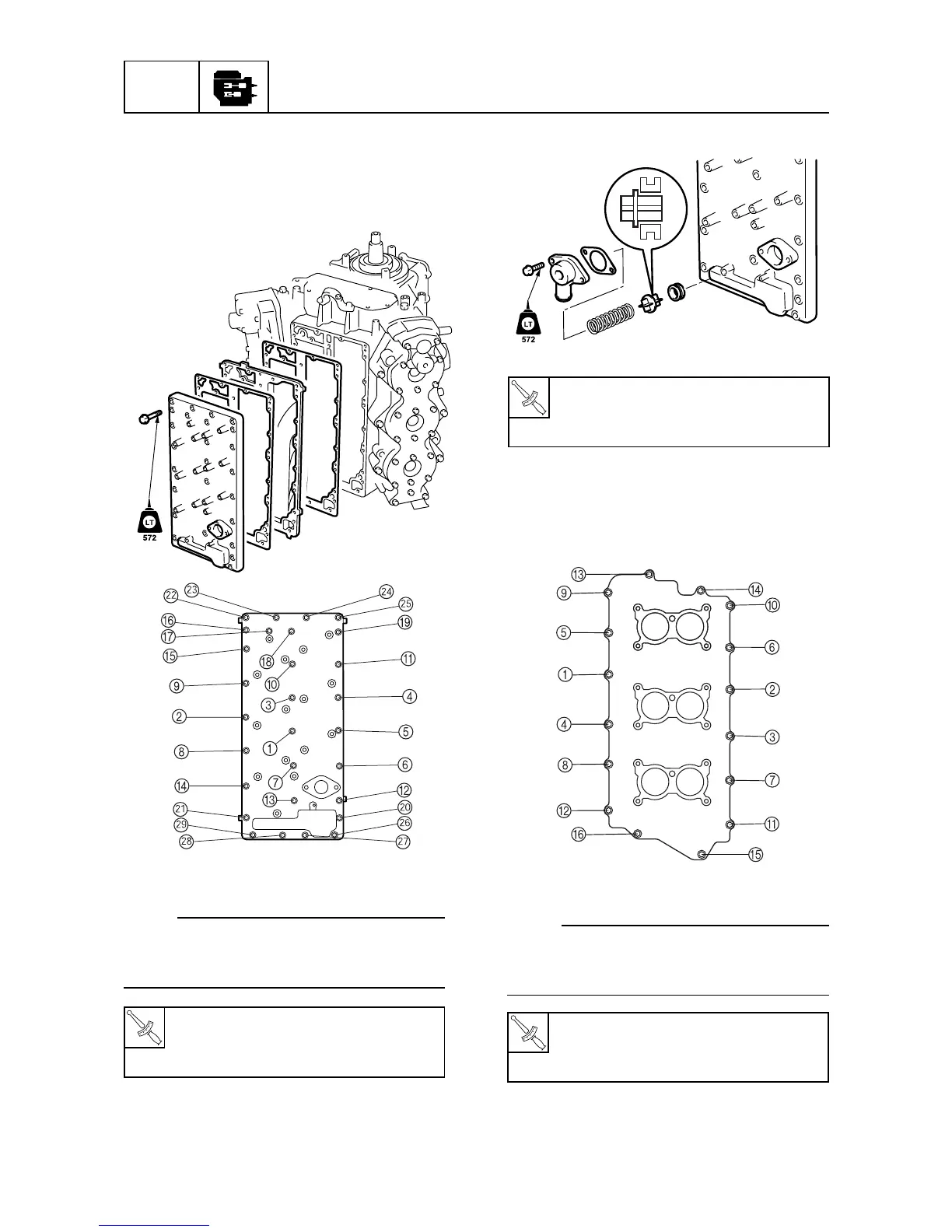
Pressure control valve cover bolt:
1st : 4 N • m (0.4 kgf • m, 3 ft • lb)
2nd : 8 N • m (0.8 kgf • m, 6 ft • lb)
T
R
.
.
Intake manifold bolt:
1st : 4 N • m (0.4 kgf • m, 3 ft • in)
2nd : 8 N • m (0.8 kgf • m, 6 ft • in)
T
R
.
.
Exhaust outer cover bolt:
1st : 4 N • m (0.4 kgf • m, 3 ft • lb)
2nd : 8 N • m (0.8 kgf • m, 6 ft • lb)
T
R
.
.
5-39
Mounting the exhaust cover
1. Install the cylinder block exhaust cover.
2. Install the exhaust outer cover, and the ex-
haust inner cover.
60H50790
60H50800
NOTE:
Tighten the exhaust outer cover bolts to the
specified torque in two stages and in the se-
quence shown.
3. Install the pressure control valve.
60H50810
Mounting the intake manifold
1. Install the reed valve plate assembly, and
the intake manifold.
60H50825
NOTE:
Tighten the intake manifold bolts to the speci-
fied torque in two stages and in the sequence
shown.
2. Install the hoses.
 Loading...