60H5E11
2
BRACKET UNIT
Upper rubber mount nut M12 71 7.1 52
Lower rubber mount nut M14 51 5.1 38
Through tube nut 7/8'' 15 1.5 11
Trim sender cam screw 2 0.2 2
Trim rod reciever nut M10 36 3.6 26
PTT
Reserver cap 0.7 0.07 0.5
Reserver mount bolt 1/4'' 5 0.5 4
Motor unit mount bolt 1/4'' 5 0.5 4
Gear housing case mount bolt 5/16'' 8 0.8 6
Gear housing bolt 3/16'' 6 0.6 4
Filter plug 6 0.6 4
Manual valve M14 3 0.3 3
Tilt cylinder end cap 130 13 94
Trim cylinder end cap 78 7.8 57
Tilt piston nut 96 9.6 71
Part to be tightened Thread size
Tightening torques
N • m kgf • m ft • lb
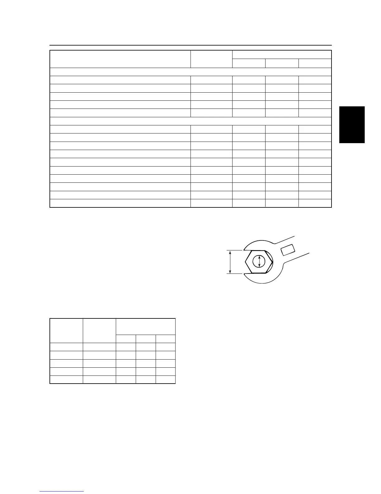
General torques
This chart specifies tightening torques for stan-
dard fasteners with a standard ISO thread
pitch. Tightening torque specifications for spe-
cial components or assemblies are provided
in applicable sections of this manual. To avoid
warpage, tighten multi-fastener assemblies in
a crisscross fashion and progressive stages
until the specified tightening torque is reached.
Unless otherwise specified, tightening torque
specifications require clean, dry threads.
Components should be at room temperature.
General torque
Nut(A) Bolt (B)
specifications
N • m kgf • m ft • lb
8mm M5 5 0.5 3.6
10mm M6 8 0.8 5.8
12mm M8 18 1.8 13
14mm M10 36 3.6 26
17mm M12 43 4.3 31
B
A
Tightening torques
2-10