60H5E11
Electrical systems
ELEC
Digital circuit tester : 90890-03174
Peak voltage adapter B : 90890-03172
NOTE:
Replace the CDI unit, if output peak voltages
of the pulser coil and the charge coil are on or
above specifications and the CDI unit output
peak voltage is below specification.
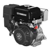
Thermoswitch 1 continuity
temperature:
Pink(P) – Black(B)
E : 84 to 90°C (183 to 194 °F)
F : 60 to 74°C (140 to 165 °F)
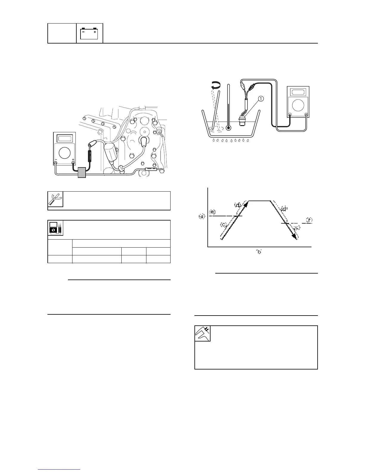
CDI unit output peak voltage :
Black/white(B/W)-ground lead
r/min
Loaded
Cranking 1,500 3,500
DC V 65 140 135
8-13
Checking the CDI unit
1. Connect the digital circuit tester lead to the
ignition coil lead and the ground lead.
2. Measure the CDI unit output peak voltage.
If the measurement is below specification,
check the lead, and measure the peak out-
put voltages of pulser coil and charge coil.
60h80150
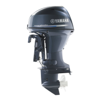
Checking the thermoswitch
1. Place the thermoswitch 1 in a container
with water and slowly heat the water.
60h80180
2. Check the thermoswitch 1 for continuity
at the specified temperature. Replace the
thermoswitch 1 if out of specification.
60h80190
NOTE:
Check both left and right thermoswitches.
A Temperature
B Time
C No continuity
D Continuity