60H5E11
3
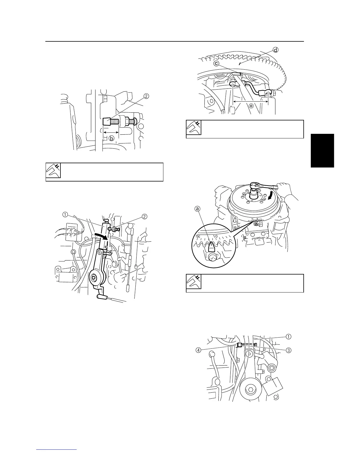
Specified length B: 25.0 mm(0.98 in)
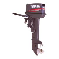
Magnet control link length E :
65mm(2.56in) (reference)
Control system
3-10
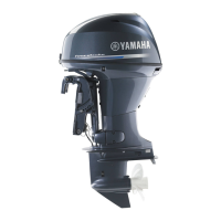
Standard ignition timing : ATDC 7°
10. Secure the timing plate 5 at the adjusted
position and mark the position with paint.
11. Adjust the fully advanced stop screw 2 so
that the stopper B has the specified length.
60H30250
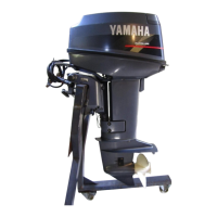
12. Move the magnet control lever 1 until it
touches the fully advanced stop screw 2.
60H30160
13. Adjust the length of magnet control link so
that the timing mark C on the flywheel
aligns with the mark D on the base assem-
bly.
60H30260
14.Turn the flywheel clockwise to align the
pointer mark A on the timing plate with
standard ignition angle on the flywheel
scale.
60H30180
15. Move the magnet control lever 1 until the
standard ignition timing adjusting screw 3
touches the fully closed stopper 4 on the
cylinder block.
60H30190