4. Install:
Lower handlebar
holder
nut
40 Nm (4.0 m-
kgf
, 29
ft
·lbf)
• Throttle
gr
ip "1"
• Throttle cabl
es
• Throttle cable housings "2"
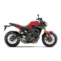
• Grip e
nd
Grip end
26 Nm (2.6
m·kgf
, 19
ft
·lbf)
TIP
~~~~~~~~~~~~~~~
• Align t
he
projection "a" on the throttle cable
hous
in
g with the hole "b"
in
the handlebar.
•T
here should be 1- 3 mm (0.04-0.12
in
) of
clearan
ce
"c" between t
he
throttle grip and t
he
grip end.
c
~
5. Install:
• Right handlebar
sw
itch
Right handlebar
switch
screw
2.0 Nm (0.20 m·
kgf
, 1.4
ft
·lbf)
TIP
~~~~~~~~~~~~~~~
Align the projection "a" on the
rig
ht handlebar
switch with t
he ho
le "b" in the handlebar.
6. Install:
• Front brake master cylinder assembly
Refer to "INSTALLING THE FRONT BRAKE
MASTER CYLINDER" on page 4-30.
7. Install:
• Clutch lever holder "1"
HANDLEBAR
• Clutch cable
Clutch lever
holder
pinch
bolt
11
Nm
(1
.1 m-kgf, 8.0 ft·lbf)
TIP
~~~~~~~~~~~~~~~
A
li
gn the center of
sl
it on the clutch lever holder
wi
th
the punch mark "a" on t
he
handleba
r.
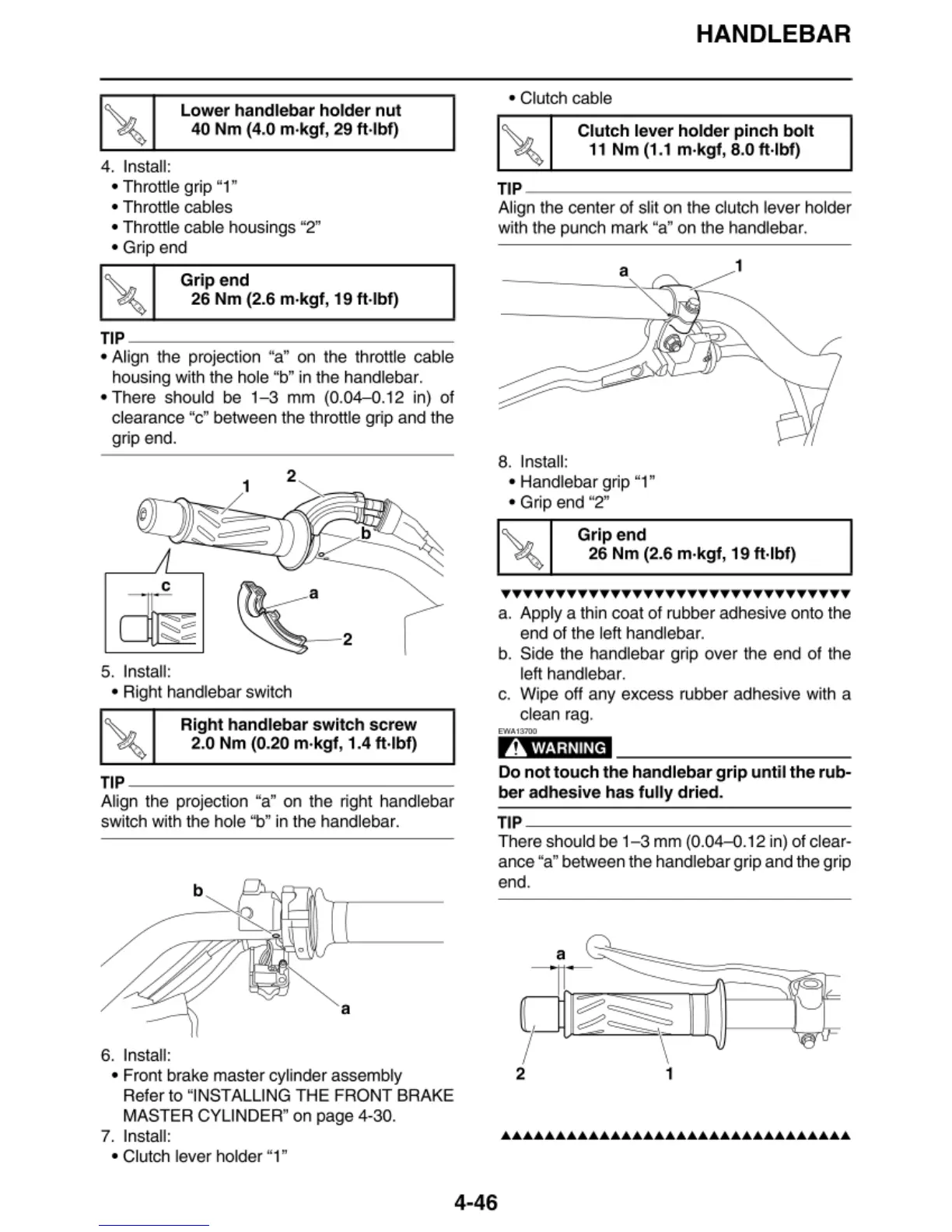
8. Insta
ll
:
• Handlebar grip "1"
•
Gr
ip end "2"
Grip end
26
Nm
(2.6 m-kgf, 19 ft·lbf)
••••••••••••••••••••••••••••••••
a. Apply a thin coat of rubber adhesive onto the
e
nd
of the left handlebar.
b.
Side the handlebar grip over the end of the
left handlebar.
c. W
ip
e off any excess rubber adhesive wi
th
a
clean rag.
EWA13700
,A
WARNING
Do
not
touch
the handlebar
grip
until the rub-
ber
adhesive has
fully
dried.
TIP
~~~~~~~~~~~~~~~
There should be
1-3
mm (0.04--0.12
in
) of clear-
ance "a" between the
ha
ndlebar
gr
ip and the
gr
ip
end.
7
2 1
4-46