CONNECTING RODS AND PISTONS
big end bearing kept in the current condition.
TIP
~~~~~~~~~~~~~~-
• Do not move the connecting
rod
or
crankshaft
unt
il
the cl
ea
rance measurement has been
completed.
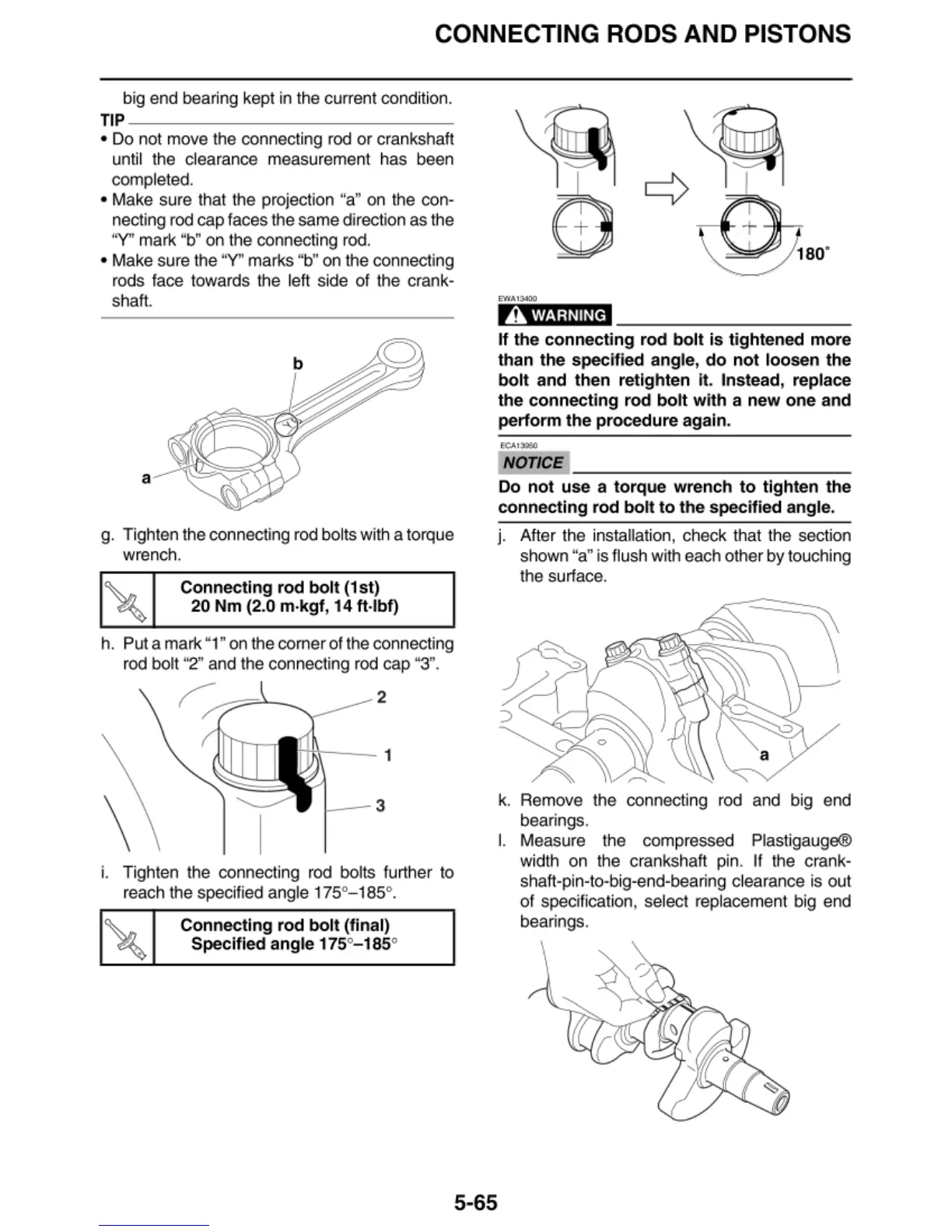
• Make sure that the projection "a"
on
the con-
necting
rod
cap faces the same direction as the
"Y'' mark "b"
on
the connecting
rod.
• Make sure the "Y" marks "b"
on
the connecting
rods
face
towards the left side of the crank-
shaft.
a
g. Tighten the connecting rod bol
ts
with a torque
wrench.
Connecting rod
bolt
(1st)
20 Nm (2.0
m·kgf
, 14
ft
·lbf)
h. Put a mark "1"
on
the corner of the connecting
rod bolt "2" and the connecting rod cap "3".
2
\
1
--
3
i.
Tighten the connecting rod bolts further
to
reach the speci
fied
angle 175°- 185°.
Connecting rod
bolt
(final)
Specified angle 175°
-1
85°
A WARNING
If the connecting rod
bo
lt
is
tigh
tened
mor
e
than the specified angle,
do
not
loosen
the
bolt
and then retighten it . Instead, replace
the
connecting rod
bolt
with
a
new
one
and
perform the procedure again.
NOTICE
~~~~~~~~~~~~~
Do
not
use a torque wrench
to
tighten the
connecting rod
bolt
to
the
specified angle.
J.
After the installation, check
th
at the section
shown "a" is
flu
sh with each other by
to
uching
the surface.
k.
Remove the con
ne
cting rod and big end
bearings.
5-65
I.
Measure
th
e compressed Plastigauge®
width on the crankshaft pin.
If
the crank-
shaft-pin-to-big-end-bearing clearance is out
of specificati
on
,
se
lect replacement big end
bearings.
 Loading...