ELECTRICAL COMPONENTS
Check
each
sw
itch for
cont
i
nu
ity with
the
pocket tester. If t
he
continui
ty
reading is incorrect,
check
the
wiring
con
nectio
ns
and if necessary, replace the switch.
NOTICE
~~~~~~~~~~~~~~~~~~~~~~~~~~~~~~~~
Never
insert
the
tester
probes
into
the
coupler
terminal
slots
"
a".
Always
insert
the
probes
from
the
opposite
end
of
the
coupler,
taking
care
not
to
loosen
or
damage
the
leads
.
Pocket
tester
90890-
03112
Analog
pocket
tester
YU-03112-C
TIP
~~~~~~~~~~~~~~~~~~~~~~~~~~~~~~~~
•
Be
f
ore
che
ck
ing for
cont
i
nu
ity,
set
the
po
ck
et tester to "
O"
and to the
"Q
x 1" ra
ng
e.
•
When
checking f
or
continuity,
sw
i
tc
h
ba
ck
a
nd
forth between the
sw
it
ch
positions a few times.
a
"oo"
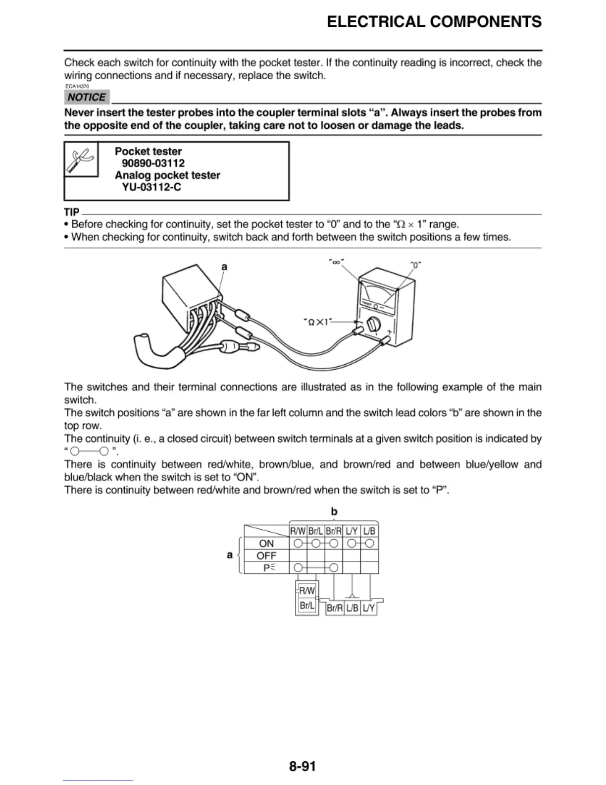
The
sw
it
ches
and their terminal connecti
ons
are
illustrated as in the followi
ng
example
of
the main
switch.
The
switch positi
ons
"a" are shown in the f
ar
left column
and
the switch lead
co
l
ors
"b" are shown in the
top
row.
The
continuity (i. e., a clo
sed
circui
t)
between swit
ch
termi
na
ls at a given switch
pos
it
io
n is i
nd
ica
ted by
'
'0-0
".
There is continuity between red/white,
brow
n
/b
lue, and
brow
n/red
and
between blue/yellow and
blu
e/b
l
ac
k
when
the
sw
itch is
set
to "
ON
".
There is conti
nu
ity between red/white
and
brown/red when the swit
ch
is
set
to
"P''.
b
---
R/W
B
r/I.
Br
/ A
IJY
lJB
ON
r
' r
l
OFF
p~
I
RNJ
-
~
Br
/I.
Br/RI
IJB
IJY
8-91
 Loading...