This is an Ethernet communications
connector that connects to a personal
computer running SigmaWin+.
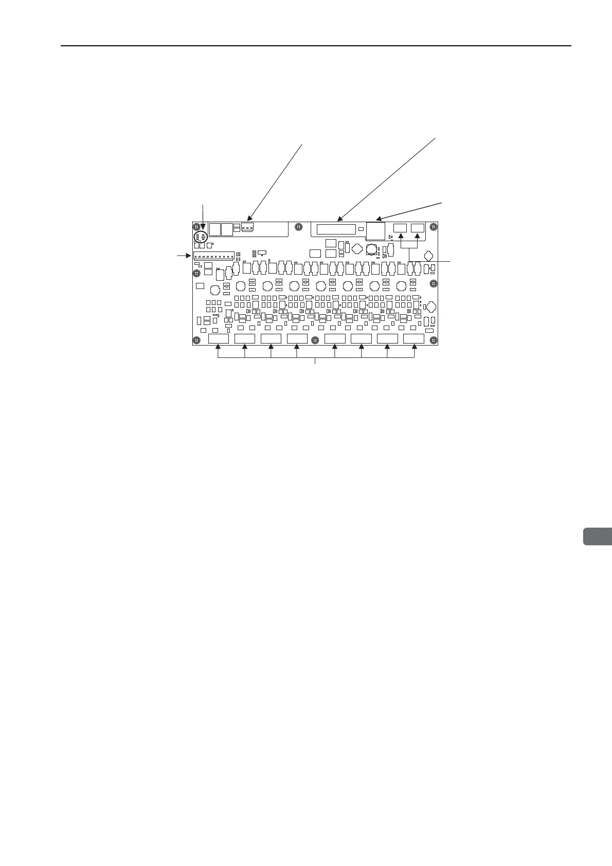
CN31 Control power supply connector
Connects the control power supply.
CN11 to CN18 Servomotor/encoder connectors
Connect the servomotors and encoders.
CN32 Main circuit
power supply connector
Connects the main circuit
power supply.
CN9 Personal computer connector
CN6A/CN6B Connectors for
MECHATROLINK-III communications
CN1 Connector for I/O signal
Used for reference input signals
and sequence I/O signals.
LED indicator (LK1, LK2, CN, CMERR, RUN, ALM)
LK1, LK2 (green): Lights during MECHATROLINK communications.
ALM (red): Lights when an alarm occurs.
CN (green): Lights when the SERVOPACK receives a CONNECT
command normally.
RUN (green): Flashes while one or more servos are ON.
Lights when the servos for all axes are OFF.
CMERR (yellow): Flashes when there is an error for a
MECHATROLINK command. Lights when there
is a communications error.
Connects devices that support
MECHATROLINK-III.
Refer to 5.4 Wiring MECHA-
TROLINK-III Communications.
Refer to 5.2 I/O Signal (CN1) Con-
nections
Refer to 5.5 Connecting the Servomotor and Encoder.
Refer to 5.1 Wiring the Main Cir-
cuit and Control Power Supplies.
Refer to 5.1 Wiring the Main Circuit
and Control Power Supplies.

 Loading...


