Parameter List
11
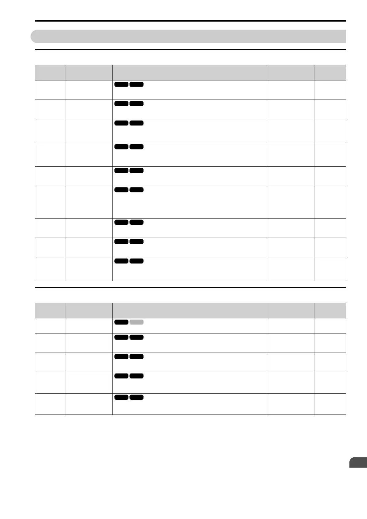
11.12 S: Elevator Parameters
YASKAWA SIEPYEULA5001C LA500 Technical Manual 267
11.12 S: Elevator Parameters
◆ S1: Brake Sequence
No.
(Hex.)
Name Description
Default
(Range)
Ref.
S1-01
(0680)
Zero Speed Level at Stop
Determines the speed to begin applying DC Injection when the drive is ramping to stop
(b1-03 = 0). Set as a percentage of the maximum output frequency (E1-04).
Determined by A1-02
(0.000 - 9.999%)
363
S1-02
(0681)
DC Injection Current at
Start
Determines the amount of current to use for DC Injection at start. Set as a percentage of
the drive rated current.
50%
(0 - 75%)
363
S1-03
(0682)
DC Injection Current at
Stop
Determines the amount of current to use for DC Injection at stop. Set as a percentage of
the drive rated current. When using OLV Control, the DC injection current is
determined by multiplying S1-03 by S3-25 or S3-26.
50%
(0 - 75%)
363
S1-04
(0683)
DC Injection Time at
Start
Determines how long the drive should perform DC Injection at start. During this time,
the drive allows motor flux to develop, which is essential for applying torque quickly
once the brake is released. A setting of 0.00 disables S1-04.
0.40 s
(0.00 - 10.00 s)
363
S1-05
(0684)
DC Injection Time at
Stop
Determines how long the drive should perform DC Injection at stop. A setting of 0.00
disables S1-05.
0.60 s
(0.00 - 10.00 s)
363
S1-06
(0685)
Brake Open Delay Time
Determines the time that must pass after an Up/Down command is entered before the
output terminal set for "Brake control" (H2-xx = 50) is triggered. Adjusting this delay
time can help when there is not enough time to develop the appropriate amount of
motor flux. Be sure to also increase the time S1-04 when setting S1-06 to relatively long
delay time.
0.20 s
(0.00 - 10.00 s)
364
S1-07
(0686)
Brake Close Delay Time
Determines the time that must pass after zero speed is reached before the output
terminal set for "Brake control" (H2-xx = 50) is released.
0.10 s
(0.00 - 10.00 s)
364
S1-10
(0687)
Run Command Delay
Time
Determines the time that must pass after zero speed is reached before the output
terminal set for "Brake control" (H2-xx = 50) is released.
0.10 s
(0.00 - 10.00 s)
364
S1-11
(0688)
Output Reactor Open
Delay Time
Determines the time that must pass for an output terminal set for “Output contactor
control” (H2-xx = 51) to be released after the drive has stopped and drive output has
been shut off.
0.10 s
(0.00 - 10.00 s)
364
◆ S2: Slip Compensation for Elevators
No.
(Hex.)
Name Description
Default
(Range)
Ref.
S2-01
(068F)
Motor Rated Speed
Sets the rated speed of the motor.
1380 rpm
(300 - 1800 rpm)
364
S2-02
(0690)
Slip Compensation Gain
in Motoring Mode
Slip compensation for leveling speed can be set separately for motoring and
regenerative states to help improve the accuracy of leveling.
0.7
(0.0 - 5.0 rpm)
364
S2-03
(0691)
Slip Compensation Gain
in Regenerative Mode
Slip compensation for leveling speed can be set separately for motoring and
regenerative states to help improve the accuracy of leveling.
1.0
(0.0 - 5.0)
364
S2-05
(0693)
Expert
Slip Compensation
Torque Detection Delay
Time
Sets a delay time before detecting torque for slip compensation.
1000 ms
(0 - 10000 ms)
365
S2-06
(0694)
Expert
Slip Compensation
Torque Detection Filter
Time Constant
Sets the filter time constant applied to the torque signal used for the slip compensation
value calculation.
500 ms
(0 - 2000 ms)
365

 Loading...


