Startup Procedure and Test Run
4
4.5 Start-up Procedures
YASKAWA SIEPYEULA5001C LA500 Technical Manual 87
WARNING! Sudden Movement Hazard. Clear personnel, secure equipment and check sequence and safety circuitry before
starting the drive. Secure covers, couplings, shaft keys, and machine loads. Ensure start/stop and safety circuits are wired
properly and in the correct state. Failure to comply can result in death or serious injury from moving equipment.
WARNING! Sudden Movement Hazard. Always check the operation of any emergency circuits after they are wired. Emergency
circuits are required to provide safe and quick shutdown of the drive. Do not operate the drive with untested emergency circuits.
Failure to comply can result in death or serious injury.
NOTICE: Equipment Hazard. The motor may run in reverse if the phase order is backward. Connect motor input terminals U/T1,
V/T2, and W/T3 to drive output terminals U/T1,V/T2, and W/T3. The phase order for the drive and motor should match.
NOTICE: Equipment Hazard. Check all the wiring including the PG encoder wiring, to ensure that all connections are correct
after installing the drive and connecting any other devices. Failure to comply could result in damage to the drive.
After applying power, the drive mode display should appear and no fault or alarm should be displayed. In the
event of a drive fault or error code, refer to Troubleshooting on page 165.
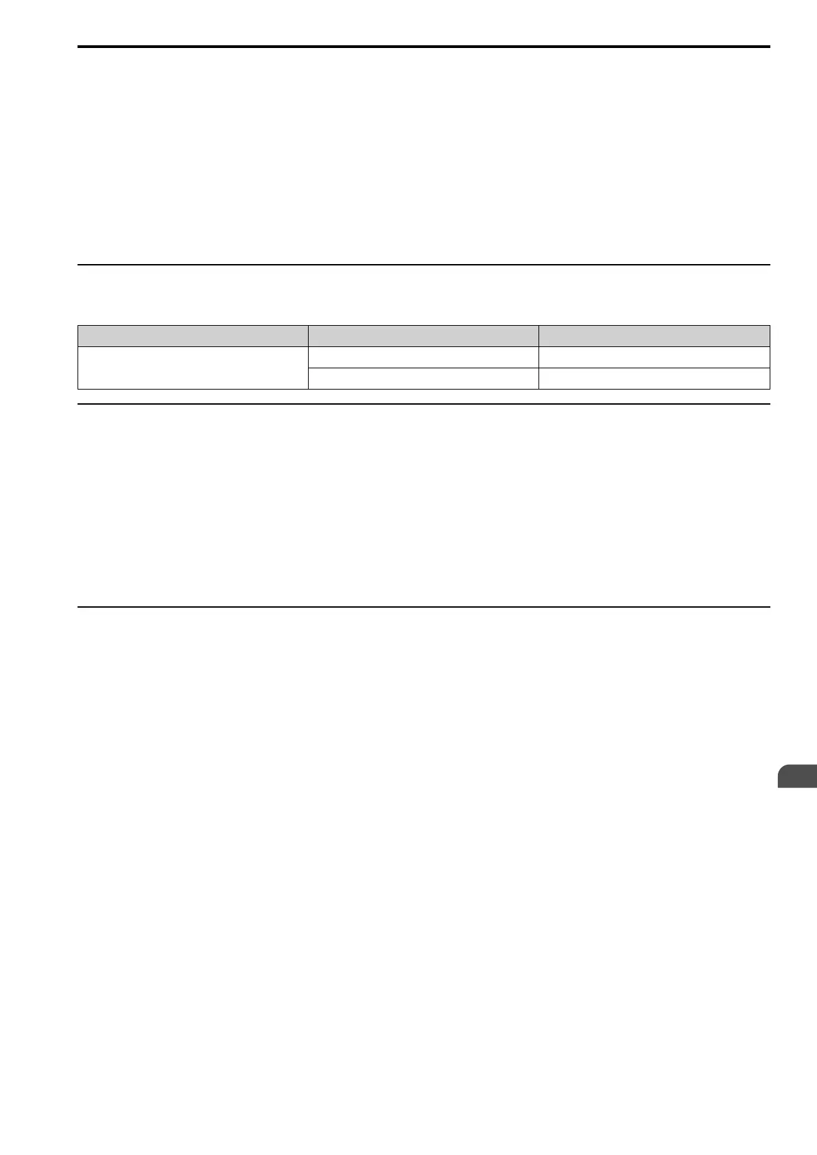
◆ Control Method Selection
Select one of the motor control methods after applying power to the drive according to the table below.
Machine Type Control Method A1-02 Setting
Induction Motor
V/f Control 0
Open Loop Vector (OLV) Control 2
◆ Motor Rotation Direction Setup
Check the direction of motor rotation to verify the Up command causes the elevator to move in the upward
direction. Perform the following check to confirm proper motor and load direction:
• The drive outputs motor voltage in U/T1-V/T2-W/T3 phase sequence when an Up command is issued. Check
the motor rotation with this phase sequence (for most motors clockwise is seen from the shaft side). If motor
rotation is incorrect, rewire the drive output to the motor.
DANGER! Electrical Shock Hazard. Do not examine, connect, or disconnect wiring on an energized drive. Before servicing,
disconnect all power to the equipment and wait for the time specified on the warning label at a minimum. The internal capacitor
stays charged after the drive is de-energized. The charge indicator LED extinguishes when the DC bus voltage decreases
below 50 Vdc. When all indicators are OFF, measure for dangerous voltages to make sure that the drive is safe. If you do work
on the drive when it is energized, it will cause serious injury or death from electrical shock.
◆ Flowchart B: Auto-Tuning for Induction Motors
Flowchart B shows Auto-Tuning for induction motors operating with V/f Control or Open Loop Vector Control.
Settings can change when the application changes.

 Loading...


