<4. WIRING>
4-12
IM 01E30D01-01EN
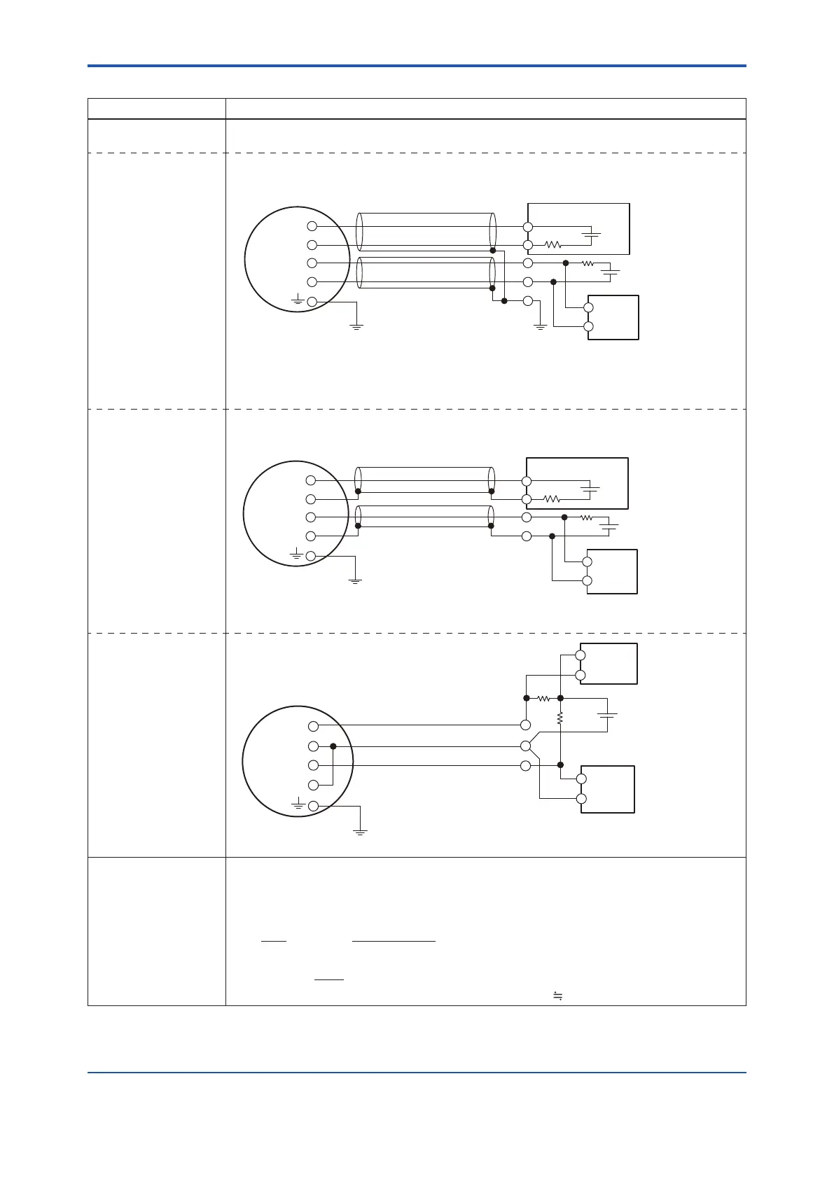
Table4.6.3 SimultaneousCurrent-PulseOutput(General-purposeUse/ExplosionProofTypeexceptTIIS)
Connection Description
Simultaneous Current-
Pulse Output
When simultaneous output of current and pulse output are used, no communication is possible
in some cases. Read the following example 1 to 3.
Example 1
In this case,
Communication is
possible (up to a
distance of 2 km when
a CEV cable is used)
and when a two-wire
shielded cable is used.
No communication is possible
when a shielded cable is not used.
However, simultaneous current-pulse output is possible.
Shielded Cable
SUPPLY
DO
Distributor, etc.
+
−
R3
+
−
+
−
R
+
−
Shielded Cable
For the shielded cables in this example,
use two-wire shielded cables
separately for SUPPLY and DO.
E1
AXR Terminal
E3:30 V DC max
Cable Resistance:R1[Ω] *9
Cable Resistance:R2[Ω] *9
0.0236 x (R1 + R2+ R3) + 14.7 ≤ E1 [V] ≤ 42
*10
In the case of R3=250[Ω]
0.0236 x (R1 + R2) + 20.6 ≤ E1 [V] ≤ 42
*10
*8
*7
*6
*3
*3: This supply voltage requires a power source
with a maximum output current of no less than E3/R.
Electric
counter
R3[Ω]:Load Resistance
Example 2
In this case,
Communication is
possible (up to a
distance of 2 km when
a CEV cable is used)
and when a one-wire
shielded cable is used.
Shielded Cable
SUPPLY
DO
Distributor, etc.
+
−
R3
+
−
+
−
R
+
−
Shielded Cable
For the shielded cables in this example,
use two-wire shielded cables
separately for SUPPLY and DO.
E1
AXR Terminal
E3
:
30 V DC max
0.0236 x (R1 + R2+ R3) + 14.7 ≤ E1 [V] ≤ 42
*10
In the case of R3=250[Ω]
0.0236 x (R1 + R2) + 20.6 ≤ E1 [V] ≤ 42
*10
*8
*7
*6
Cable Resistance:R1[Ω] *9
Cable Resistance:R2[Ω] *9
Electric
counter
R3[Ω]:Load Resistance
*4
*4: This supply voltage requires a power source
with a maximum output current of no less than E3/R.
Example 3
In this case,
No communication is
possible when a three-
wire cable is used.
R
250Ω
E5
0.0236×﴾R1
+
R2﴿
+
20.6≤E5
[
V
]
≤30
*7
*5: This supply voltage requires a power source
with a maximum output current of no less than (E5/R+0.0236).
SUPPLY
DO
+
−
+
−
AXR Terminal
*8
Electric
counter
+
−
Recorder
or other
instrument
−
*6
*5
Cable Resistance
:
R2[Ω] *9
Cable Resistance
:
R1[Ω] *9
The range of load
resistance R for the
pulse output
TherangeofloadresistanceRforthepulseoutputmustbasicallybe1kΩand2W.Theload
resistance should be selected by calculation as shown below when proper transmission is
impossible due to the length of cable or frequency of pulse output.
P (mW) =
…………………………
(2)
R (kΩ)
E
2
(V)
≤ R (kΩ) ≤
…
(1)
120
E (V)
C (μF) × f (kHz)
0.1
E: Supply voltage (V)
f: Frequency of pulse output (kHz)
R:Valueofloadresistance(kΩ)
C:Cablecapacitance(μF)
P: Electrical power of the load resistance (mW)
Note: C
0.1(μF/km)forCEVcable
Note: •ThecommunicationispossiblethoughitmightnotmeetapartoftheHARTcommunicationspecicationdependingonuseconditions.
•Whenusingcurrentandpulseoutputsimultareously,theHARTcommunicationmaybeinuencedbynoisecomparinganalogoutput
only.

 Loading...

