<4. WIRING>
4-13
IM 01E30D01-01EN
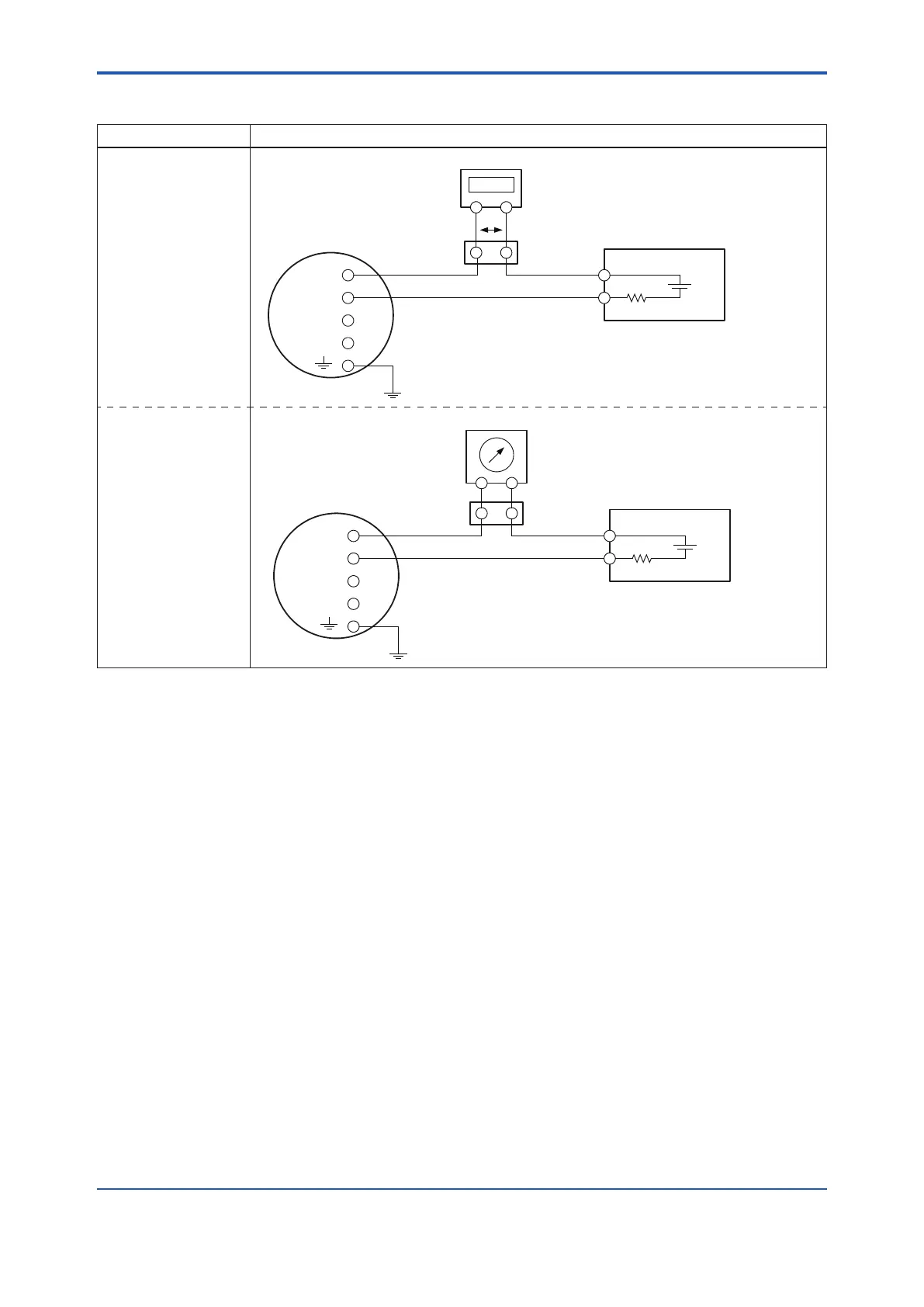
Table4.6.4 DigitalExternalIndicatorUsingCurrentOutput(General-purposeUse/ExplosionProofTypeexcept
TIIS)
Connection Description
Current Output
Example 1
Connection to digital
external indicator
SUPPLY
DO
Distributor, etc.
+
-
R3
+
-
+
-
AXR Terminal
E1
Cable Resistance
:
R1[Ω]
*9
Cable Resistance:R4[Ω] *9
0.0236 × (R1 + R2 + R3 + R4) + V2 + 14.7 ≤ E1 [V] ≤ 42
*10
In the case of R3 = 250 [Ω]
0.0236 × (R1 + R2 + R4) + V2 + 20.6 ≤ E1 [V] ≤ 42
*10
+-
Cable Resistance
:
R2[Ω]
*9
Digital External Indicator
Relaying
terminal
77.7%
V2: Voltage between terminals of External Indicator
V2
Transmission of AXR
output might fail when
the external indicator
breakdown occurs.
R3[Ω]:
Load Resistance
Example 2
Connection to analog
external indicator
Cable Resistance
:
R1[Ω]
*9
Cable Resistance:R4[Ω] *9
Cable Resistance
:
R2[Ω]
*9
Transmission of AXR
output might fail when
the external indicator
breakdown occurs.
SUPPLY
DO
Distributor, etc.
+
-
R3
+
-
+
-
AXR Terminal
E1
+-
Analog External Indicator
Relaying
terminal
Internal resistance 10 Ω or less
0.0236 × (R1 + R2 + R3 + R4 + 10) + 14.7 ≤ E1 [V] ≤ 42
*10
In the case of R3 = 250 [Ω]
0.0236 × (R1 + R2 + R4 + 10 ) + 20.6 ≤ E1 [V] ≤ 42
*10
R3[Ω]:
Load Resistance
*6: Toavoidtheinuenceofexternalnoise,useanelectriccounterwhichtstothepulsefrequency.
*7: Resistor is not necessary in the case of an electric counter which can receive contact pulse signal directly.
*8: GroundtheAXRtoavoidthecurrentoutputerrorinsimultaneouscurrent-pulseoutput.
*9: Calculatethecableresistancebyusingthefollowingasaroughguideline:10.9Ωper1kmforthecablewiththecrosssectionof
2 mm
2
,19.5Ωper1kmforthecablewiththecrosssectionof1.25mm
2
.
*10: Themaximumvoltageis32VDCinthecaseofLightningProtectorspecication(optionalcodeA).

 Loading...

