<4. WIRING>
4-15
IM 01E30D01-01EN
Connection Description
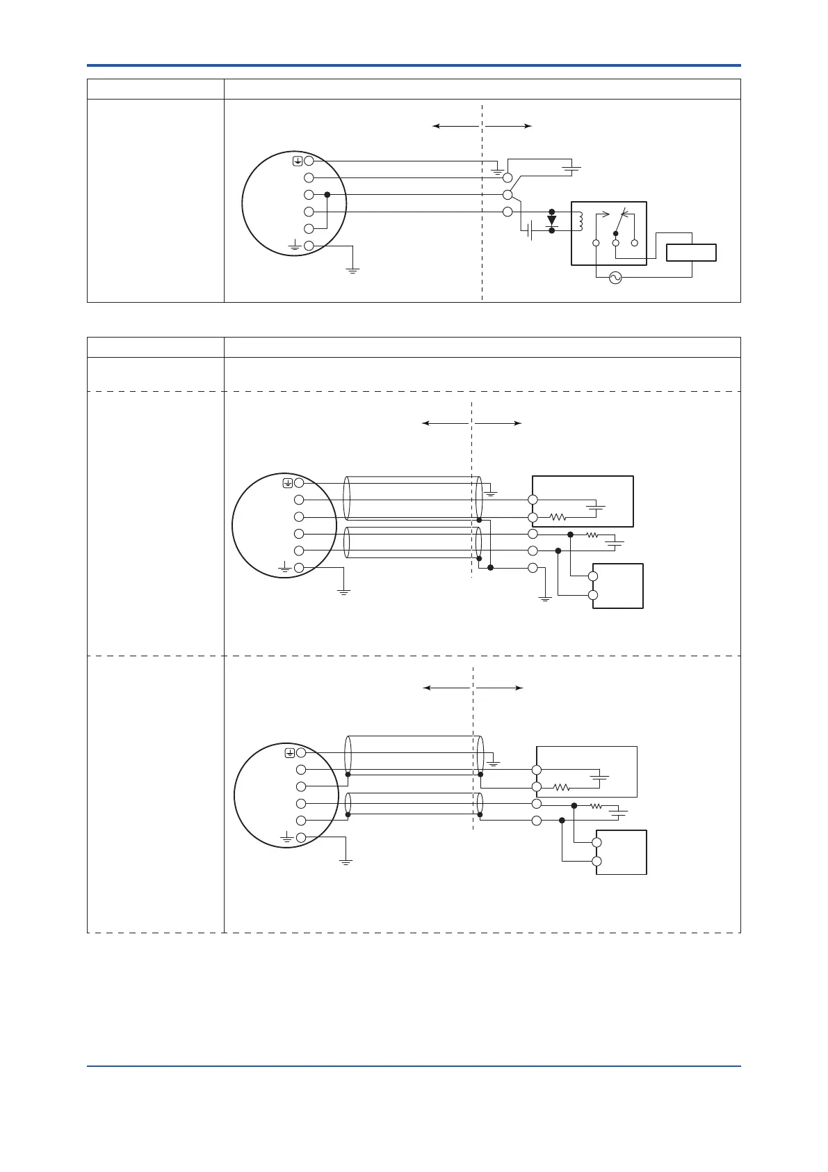
Status Output
Alarm Output
In this case,
No communication is
possible when a four-
wire cable is used.
Cable Resistance:R1[Ω] *9
Cable Resistance:R2[Ω] *9
Magnetic
valve
Relay
AC Power Supply
AXR Terminal
0.0236×﴾R1
+
R2﴿
+
14.7
≤E2
[
V
]
≤42
*10
E2
JIS Class A
SUPPLY
DO
Hazardous area Non-hazardous area
+
−
+
−
Grounding resistance
of 100 Ω or less (When
the optional code A is
selected: grounding
resistance of 10 Ω)
External
Power Supply
30 V DC,
120 mA max
Table 4.6.6 Simultaneous Current-Pulse Output (TIIS Explosion Proof Type)
Connection Description
Simultaneous
Current-Pulse Output
When simultaneous output of current and pulse output are used, no communication is possible
in some cases. Read the following example 1 to 3.
Example 1
In this case,
Communication is
possible (up to a
distance of 2 km
when a CEV cable
is used) and when a
two-wire or three-
wire shielded cable
is used.
No communication is possible
when a shielded cable is not used.
However, simultaneous current-pulse output is possible.
Shielded Cable
Distributor, etc.
R3
R
Shielded Cable
For the shielded cables in this example,
use two-wire shielded cables
separately for SUPPLY and DO.
E1
AXR Terminal
E3:30 V DC max
*8
*7
*6
*3
*3: This supply voltage requires a power source with a maximum output current of no less than E3/R.
Electric
counter
R3[Ω]:Load Resistance
JIS Class A
SUPPLY
DO
0.0236 x (R1 + R2+ R3) + 14.7 ≤ E1 [V] ≤ 42
*10
In the case of R3=250[Ω]
0.0236 x (R1 + R2) + 20.6 ≤ E1 [V] ≤ 42
*10
Cable Resistance:R1[Ω] *9
Cable Resistance:R2[Ω] *9
+
−
+
−
+
−
+
−
Hazardous area Non-hazardous area
Grounding resistance of 100 Ω or less
(When the optional code A is selected:
grounding resistance of 10 Ω)
Example 2
In this case,
Communication is
possible (up to a
distance of 2 km
when a CEV cable
is used) and when a
one-wire or two-wire
shielded cable is
used.
Shielded Cable
Distributor, etc.
R3
R
Shielded Cable
For the shielded cables in this example,
use two-wire shielded cables
separately for SUPPLY and DO.
E1
AXR Terminal
E3
:
30 V DC max
0.0236 x (R1 + R2+ R3) + 14.7 ≤ E1 [V] ≤ 42
*10
In the case of R3=250[Ω]
0.0236 x (R1 + R2) + 20.6 ≤ E1 [V] ≤ 42
*10
*7
*6
*4:
This supply voltage requires a power source with a maximum output current of no less than E3/R.
R3[Ω]:Load Resistance
*4
JIS Class A
*8
SUPPLY
DO
Cable Resistance:R1[Ω] *9
Cable Resistance:R2[Ω] *9
Hazardous area Non-hazardous area
Electric
counter
+
−
+
−
+
−
+
−
Grounding resistance of 100 Ω or less
(When the optional code A is selected:
grounding resistance of 10 Ω)

 Loading...

