<4. WIRING>
4-16
IM 01E30D01-01EN
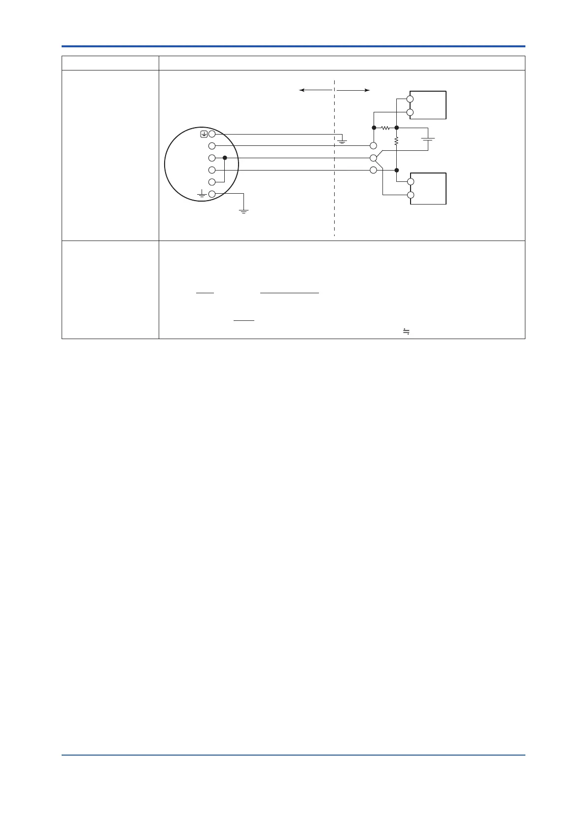
Connection Description
Example 3
In this case,
No communication is
possible when a four-
wire cable is used.
R
250Ω
E5
0.0236×﴾R1
+
R2﴿
+
20.6≤E5
[
V
]
≤30
*7
AXR Terminal
Electric
counter
+
*6
*5
JIS Class A
*8
SUPPLY
DO
Cable Resistance
:
R1[Ω] *9
Cable Resistance
:
R2[Ω] *9
Recorder
or other
instrument
+
−
+
−
+
−
Hazardous area
Non-hazardous area
*5: This supply voltage requires a
power source with a maximum
output current of no less than (E5/R+0.0236).
Grounding resistance
of 100 Ω or less (When
the optional code A is
selected: grounding
resistance of 10 Ω)
−
The range of load
resistance R for the
pulse output
TherangeofloadresistanceRforthepulseoutputmustbasicallybe1kΩand2W.Theload
resistance should be selected by calculation as shown below when proper transmission is
impossible due to the length of cable or frequency of pulse output.
P (mW) =
…………………………
(2)
R (kΩ)
E
2
(V)
≤ R (kΩ) ≤
…
(1)
120
E (V)
C (μF) × f (kHz)
0.1
E: Supply voltage (V)
f: Frequency of pulse output (kHz)
R:Valueofloadresistance(kΩ)
C:Cablecapacitance(μF)
P:
Electrical power of the load resistance (mW)
Note: C 0.1(μF/km)forCEVcable
Note: •ThecommunicationispossiblethoughitmightnotmeetapartoftheHARTcommunicationspecicationdependingonuse
conditions.
•Whenusingcurrentandpulseoutputsimultanously,theHARTcommunicationmaybeinuencedbynoisecomparinganalog
output only.

 Loading...

