<4. WIRING>
4-17
IM 01E30D01-01EN
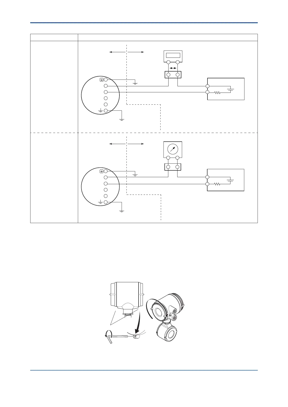
Table 4.6.7 Digital External Indicator Using Current Output (TIIS Explosion Proof Type)
Connection Description
Current Output
Example 1
Connection to digital
external indicator
Distributor, etc.
+
R3
E1
Cable Resistance
:
R1[Ω]
*9
Cable Resistance:R4[Ω] *9
0.0236 × (R1 + R2 + R3 + R4) + V2 + 14.7 ≤ E1 [V] ≤ 42
*10
In the case of R3 = 250 [Ω]
0.0236 × (R1 + R2 + R4) + V2 + 20.6 ≤ E1 [V] ≤ 42
*10
Cable Resistance
:
R2[Ω]
*9
Digital External Indicator
Relaying
terminal
77.7%
V2: Voltage between terminals of External Indicator
V2
R3[Ω]:Load Resistance
JIS Class A
Hazardous area Non-hazardous area
AXR Terminal
SUPPLY
DO
Transmission of AXR
output might fail when
the external indicator
breakdown occurs.
+
-
+
-
+-
-
Grounding resistance
of 100 Ω or less
(When the optional
code A is selected:
grounding resistance
of 10 Ω)
Example 2
Connection to analog
external indicator
Cable Resistance:R4[Ω] *9
Distributor, etc.
R3
E1
0.0236 × (R1 + R2 + R3 + R4 + 10) + 14.7 ≤ E1 [V] ≤ 42
*10
In the case of R3 = 250 [Ω]
0.0236 × (R1 + R2 + R4 + 10 ) + 20.6 ≤ E1 [V] ≤ 42
*10
Analog External Indicator
Internal resistance 10 Ω or less
R3[Ω]:Load Resistance
JIS Class A
AXR Terminal
SUPPLY
DO
Relaying
terminal
Transmission of AXR
output might fail when
the external indicator
breakdown occurs.
+
-
+
-
+
-
+-
Cable Resistance
:
R1[Ω]
*9
Cable Resistance
:
R2[Ω]
*9
Hazardous area Non-hazardous area
Grounding resistance
of 100 Ω or less
(When the optional
code A is selected:
grounding resistance
of 10 Ω)
*6: Toavoidtheinuenceofexternalnoise,useanelectriccounterwhichtstothepulsefrequency.
*7: Resistor is not necessary in the case of an electric counter which can receive contact pulse signal directly.
*8: GroundtheAXRtoavoidthecurrentoutputerrorinsimultaneouscurrent-pulseoutput.
*9: Calculatethecableresistancebyusingthefollowingasaroughguideline:10.9Ωper1kmforthecablewiththecrosssectionof
2 mm
2
,19.5Ωper1kmforthecablewiththecrosssectionof1.25mm
2
.
*10: Themaximumvoltageis32VDCinthecaseofLightningProtectorspecication(optionalcodeA).
(5) Installing the Cover
Installthecovertotheowmeterbyturningitinthedirectionofthearrowasshownbelow.Tightencover
locking screws counterclockwise using a hexagonal wrench (nominal size 3) to lock the cover (in case of
explosion proof type).
Explosion proof type
General purpose types
Front
side
Figure 4.6.5 Installing the Terminal Box Cover

 Loading...

