<6. PARAMETER DESCRIPTION>
6-28
IM 01E30D01-01EN
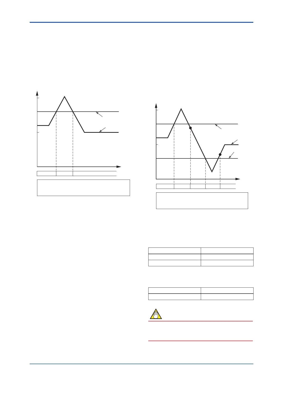
Output Example 2
Thehighalarm(H)issetto80%ormoreoftheow
rate span only without low alarm (L) setting; and the
H/L alarm hysteresis width is set to 0%.
Settings are:
G10: Low Alarm=-105%
• Asettingvalueof-105%indicatesthatthe
alarm is disabled.
G11: High Alarm=80%
G12:H/LAlarmHys=0%
0
Instantaneous flow rate
50
80
Select “H/L Alarm” for F10: DO Function
Select “Closed (On) Act” for F11: DO Active Mode
Select “Yes” for G28: Alm-H/L
High Alarm
DO Open Closed Open
[G12:H/LAlarmHys] Setting of upper/lower alarm
value hysteresis width
This parameter sets the hysteresis width for upper
and lower alarm value, using a % value of the
maximum span.
Output Example
The hysteresis width is set to 5%.
Settings are:
G10: Low Alarm=30%
G11: High Alarm=80%
G12:H/LAlarmHys=5%
0
35%
Instantaneous flow rate
30
50
80
Select “H/L Alarm(O)” for F10: DO Function
Select “Closed (On) Act” for F11: DO Active Mode
Select “Yes” for G28: Alm-H/L
High Alarm
Low Alarm
75%
DO Open Closed Open OpenClosed
[G20: 4-20mA System Alarm] Display of the
current output during a system alarm occurrence
This parameter displays the current output during a
system alarm occurrence.
Display Function
3.2 mA(Read IM) Fixed at 3.2 mA or less
21.6 mA(Read IM) Fixed at 21.6 mA or more
The default parameter is set to the following table at
the factory.
Standard Optional code C1
21.6 mA(Read IM) 3.2 mA(Read IM)
NOTE
Thedirectionofcurrentoutputcanbemodied
when a system alarm occurs. Read Subsection
11.3.1.

 Loading...

