Page 104 February 2020 – TD 266 OPERATING MANUAL – ZPulse® DCS 4420/4830/4520/4930
CHAPTER 8 Other details
8.1 Block schematic of ZPulse
®
DCS
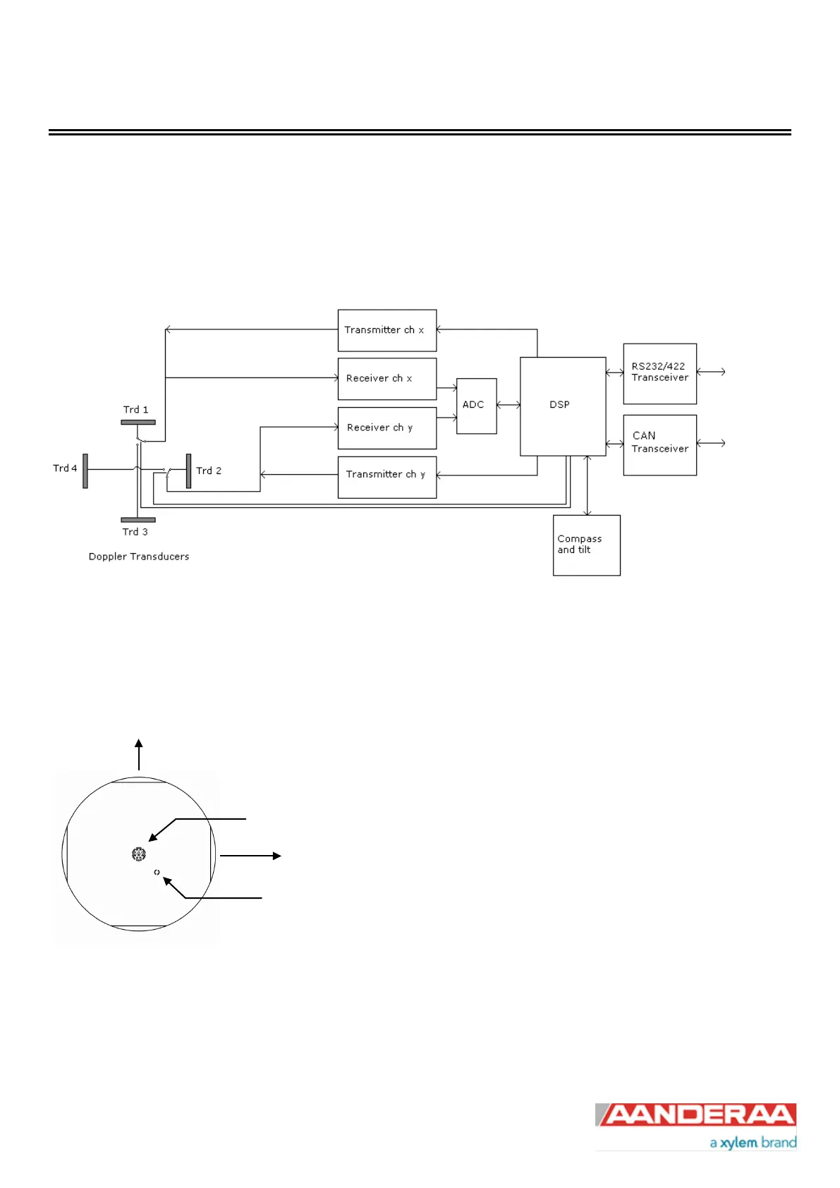
The four transducers are placed with 90˚ spacing around the transceiver head, i.e. two and two transducers are placed
on the same axis. The axis formed by Transducer 1 and 3 are called the X-axis and the axis formed by Transducer 2
and 4 are called the Y-axis, refer Figure 8-1 for a block schematic illustration measurement process and Figure 8-2 for
an illustration of the sensor orientation.
Figure 8-1 Block schematic illustration of the ZPulse
TM
DCS measurement process.
Figure 8-2 Orientation of DCS 4420/4830/4520/4930-series; top view.