February 2020 – TD 266 OPERATING MANUAL – ZPulse® DCS 4420/4830/4520/4930 Page 89
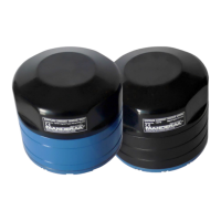
Figure 6-2 ZPulse® DCS Communication RS-422
6.3 RS-422 transmission line explained
RS-422 has differential transmission lines with twisted pairs. The sensor signals are less influenced by external noise
than with RS-232 serial communication, which makes it possible to use longer cables.
RS-422 has one balanced signal pair for the transmitted signal, TxD (also called TxD+ and TxD-) and one balanced
signal pair for the received signal, RxD (also called RxD+ and RxD-).
RxD+ and TxD+ are often named B and called non-inverting input and output, respectively.
RxD- and TxD- are often named A and called inverting input and output, respectively.
The EIA standard uses the notation A and B as described above; many manufacturers of signal converters uses the
opposite naming (A for non-inverting input/output, and B on inverting input/output) which is not correct.
Note! Always ensure which signal is non-inverting and which is inverting.
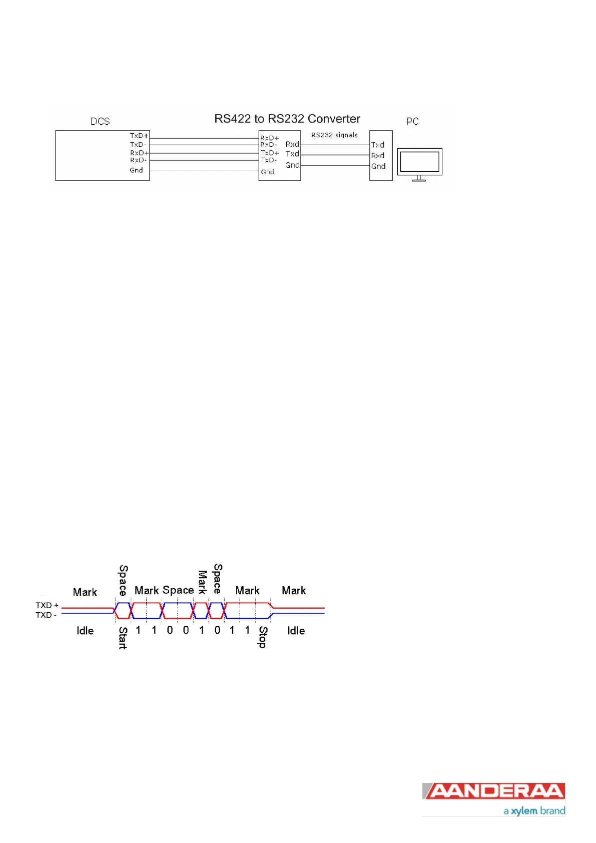
Figure 6-3 illustrates the balanced signals of a RS-422 line during transmission of a byte. The non-inverting signal is
called TxD+ while the inverting signal is called TxD-.
Figure 6-3: RS-422 transmission of a byte