Connecting a PC
A PC (with eg. the Drive composer PC tool) can be connected as follows:
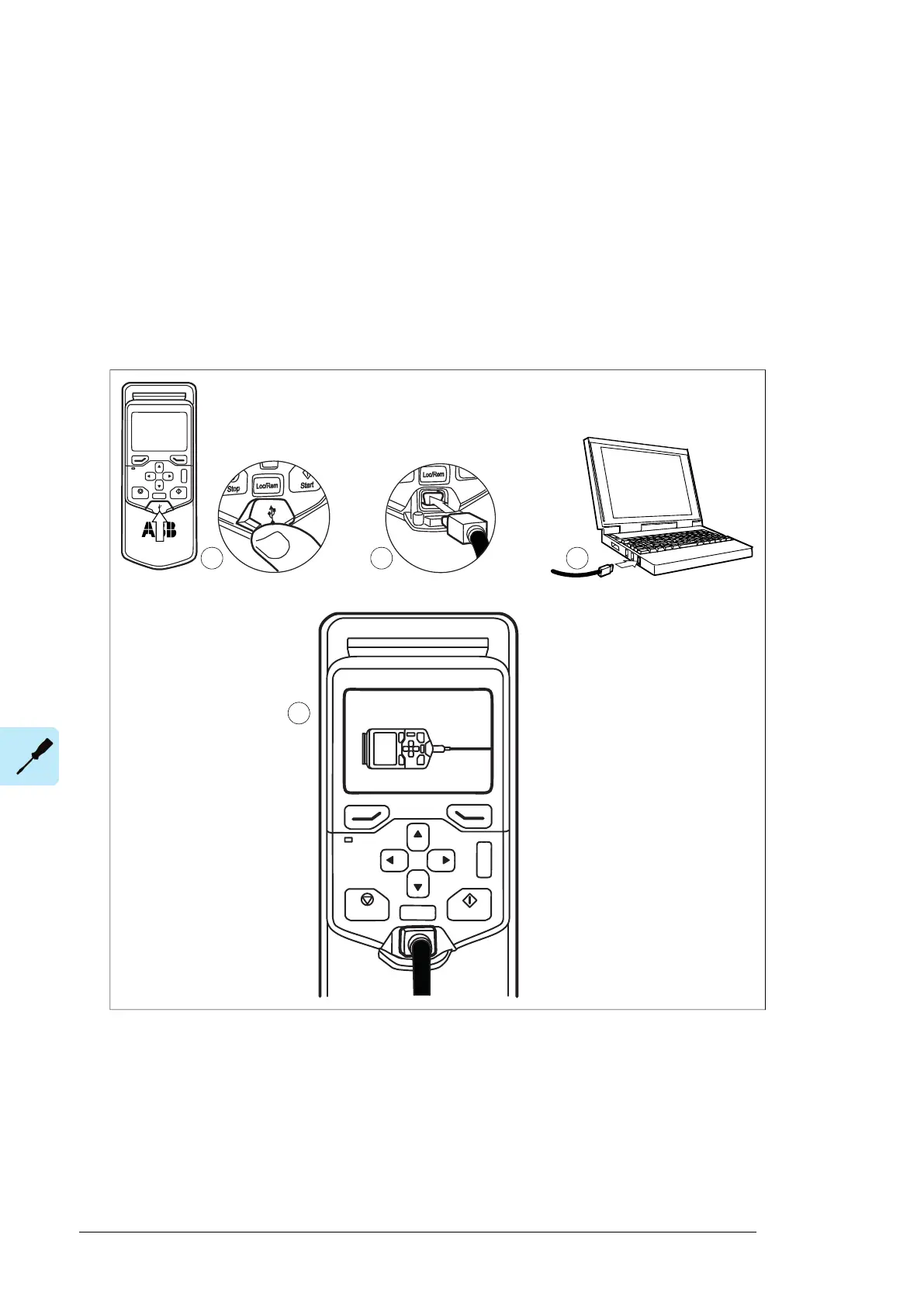
1. Connect an ACS-AP-W or ACS-AP-I control panel to the unit either
• by inserting the control panel into the panel holder or platform (if present), or
• by using an Ethernet (eg. CAT5E) networking cable.
2. Remove the USB connector cover on the front of the control panel.
3. Connect an USB cable (Type A to Type Mini-B) between the USB connector on the
control panel (3a) and a free USB port on the PC (3b).
4. The panel will display an indication whenever the connection is active.
122 Electrical installation
Connecting a PC
A PC (with eg. the Drive composer PC tool) can be connected to the inverter unit as
follows:
1. Connect an ACS-AP-I control panel to the inverter control unit either by using
an
Eth
ernet (eg. CAT5E) networking cable, or by inserting the panel into the pane
l holder
(if present).
WARNING! Do not connect the PC directly to the control panel connector of the
inverter unit as this can cause damage.
2. Remove the USB connector cover on the front of the control panel.
3. Connect an USB cable (Type A to Type Mini-B) between the USB connector on the
control panel (3a) and a free USB port on the PC (3b).
4. The panel will display an indication whenever the connection is active.
5. See the documentation of the PC tool for setup instructions.
?
Start
Stop
Loc/Rem
USB connected
5. See the documentation of the PC tool for setup instructions.
Panel bus (Control of several units from one control panel)
One control panel (or PC) can be used to control several drives by constructing a panel
bus. This is done by daisy-chaining the panel connections of the drives. Some drives have
the necessary panel connectors in the control panel holder. Others, including the
ACS880-07CLC, require the installation of an FDPI-02 module (available separately). For
100 Electrical installation

 Loading...


