Connecting the motor cables (units with common motor
terminal cubicle)
■ Output busbars
If the drive is equipped with option +H359, the motor cables connect to a common motor
terminal cubicle.
The location and dimensions of the busbars for either case are visible in the dimensional
drawings delivered with the drive, as well as the example dimension drawings in the manual.
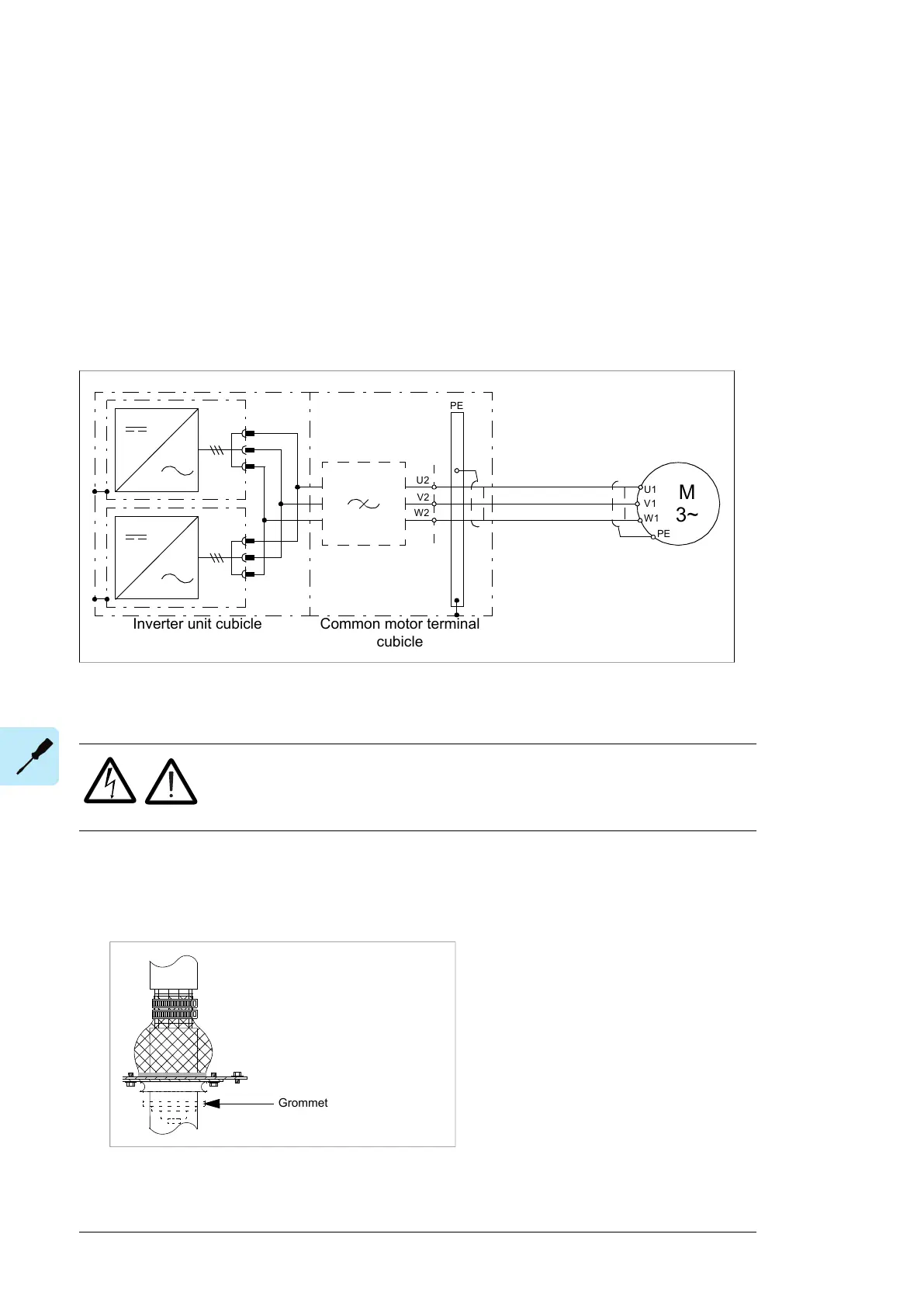
■ Connection diagram
Inverter unit cubicle Common motor terminal
cubicle
The recommended cable types are given in chapter Technical data.
■ Procedure
WARNING!
Obey the instructions in chapter Safety instructions. If you ignore them,
injury or death, or damage to the equipment can occur.
1.
Do the steps in section Electrical safety precautions (page 16) before you start the work.
2. Open the door of the cubicle and remove the shrouding.
3. Lead the cables into the cubicle. Make the 360° earthing arrangement at the cable entry
as shown.
118 Electrical installation
3. Lead the cables into the cubicle. Make the 360° earthing arrangement at the cable
entry as shown.
4.
Cut the cables to suitable length. Strip the cables and conductors.
5. Twist the cable screens into bundles and connect the bundles to the PE busbar in th
e
cubicle.
6.
Connect any separate ground conductors/cables to the PE busbar in the cubicle.
7. Connect the phase conductors to the output terminals. Use the torques specified
under Tightening torques (page 199).
8. Refit any shrouding removed earlier and close the cubicle doors.
9. At the motor, connect the cables according to instructions from the
motor
manufacturer
. Pay special attention to the phase order. For minimum radio-frequen
cy
in
terference, ground the cable shield 360 degrees at the lead-through of
the motor
terminal box,
or ground the cable by twisting the shield so that the flatten
ed shield is
wider than
1/5 of its length.
Connecting an external brake resistor assembly
See section Electrical installation of custom brake resistors (page 267).
For the location of the terminals, refer to the dimension drawings delivered with the unit or
the dimension drawing examples in chapter Dimensions.
4. Cut the cables to suitable length. Strip the cables and conductors.
92 Electrical installation

 Loading...


