Connecting the input power cables
■ Connection diagrams
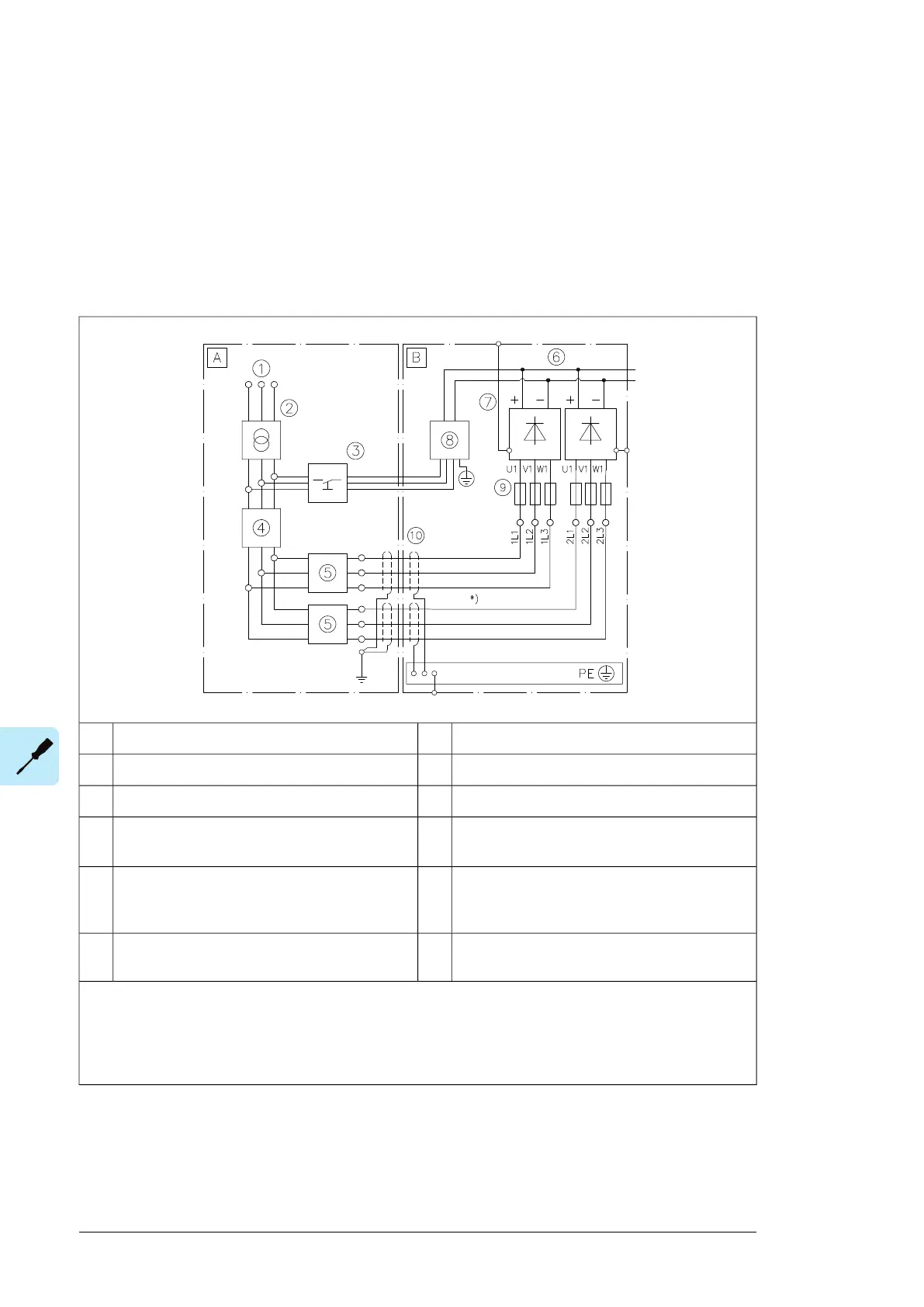
The connection diagrams below show the input power connections as well as the external
equipment required. The diagrams are simplified. The designer of the drive system must
provide the final, detailed circuit diagrams to the installer.
Connection diagram – 2×D8D, 6-pulse, internal charging
Supply unit cubicle of driveBExternal installation outside drive cabinetA
DC link6Medium voltage/low voltage switchboard1
Supply modules7Supply transformer2
Charging circuit (option +F272)8Charging switchgear including:3
• Disconnecting device
AC fuses9Supply switchgear including:4
• Disconnecting device
• Breaker/contactor
360 degrees grounding10Overcurrent and short-circuit protection of input
cabling
5
Note:
*) Use symmetrical supply cabling to ensure equal current sharing between parallel diode bridges. Required
minimum length of the cables is 5 meters.
For cable and component selection information, see chapter Guidelines for planning the electrical installation.
94 Electrical installation

 Loading...


