100 200 300
0.0
0.5
1.0
1.5
2.0
2.5
3.0
l (m)
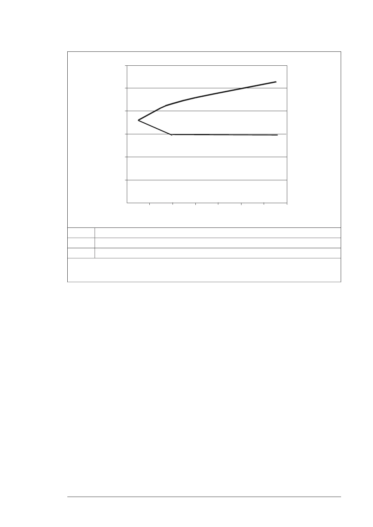
du/dt
U
N
-------------(1/Ps)
Û
LL
/U
N
Motor cable length
I
Relative peak line-to-line voltage
Û
LL
/U
N
Relative du/dt value(du/dt)/U
N
Note:
Û
LL
and du/dt values are approximately 20% higher during resistor braking.
Selecting the power cables
■ General rules
Select the input power and motor cables according to local regulations. Obey these rules:
• Select a cable capable of carrying the nominal current.
• Select a cable rated for at least 70 °C maximum permissible temperature of conductor
in continuous use.
• The inductance and impedance of the PE conductor/cable (grounding wire) must be
rated according to permissible touch voltage appearing under fault conditions (so that
the fault point voltage will not rise excessively when a ground fault occurs).
• 600 V AC cable is accepted for up to 500 V AC. 750 V AC cable is accepted for up to
600 V AC. For 690 V AC rated equipment, the rated voltage between the conductors
of the cable should be at least 1 kV.
• With US installations, consider the additional US requirements.
Use symmetrical shielded input power cables. The cabling has to be identical (length and
cross-sectional area) between all the parallel-connected supply modules. Each module
must have its own shielded 3-conductor input AC cable with the minimum length of 5 m
(16.4 ft). This ensures uniform loading of all the three input phases. Single-conductor cables
cannot be used.
Guidelines for planning the electrical installation 71

 Loading...


