Internal cooling circuit 131
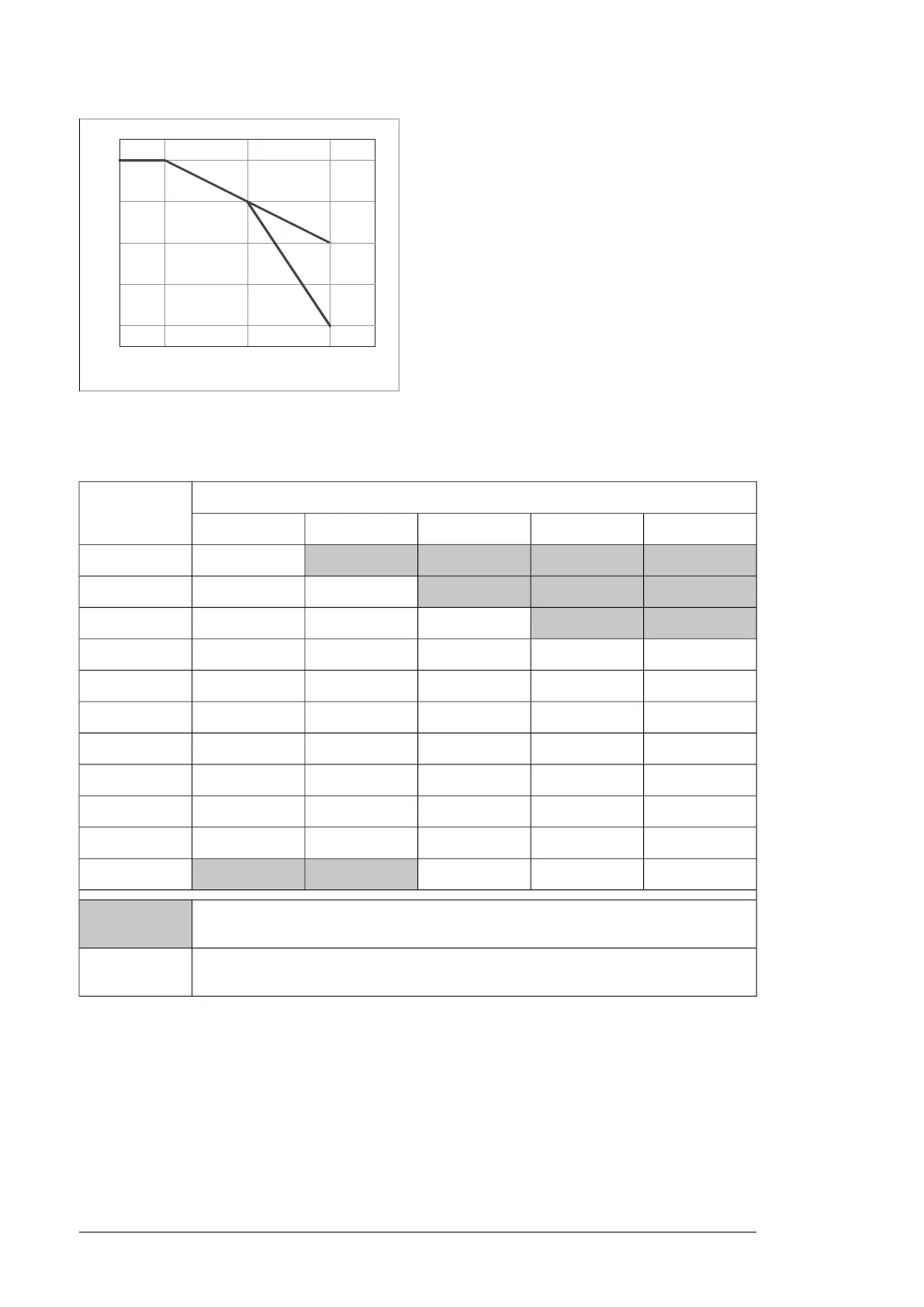
The drawing below shows the derating factor (k) in relation to coolant temperature.
Condensation is not allowed. The minimum coolant temperature to avoid condensation (at
an atmospheric pressure of 1 bar) is shown below as a function of relative humidity (f) and
ambient temperature (T
air
).
Maximum temperature rise: Depends on heat losses and mass flow. Typically 5 °C
(9 °F) with nominal losses and flow.
Pressure limits
Base pressure: 100 … 150 kPa (recommended); 200 kPa (maximum). “Base pressure”
denotes the pressure of the system compared with the atmospheric pressure when the
cooling circuit is filled with coolant.
Air counterpressure in the expansion tank: 40 kPa
Design pressure: 600 kPa
Nominal pressure difference (between main in/out lines): 120 kPa
Maximum pressure difference (between main in/out lines): 200 kPa
T
air
(°C)
Min. T
coolant
(°C)
I = 95% I = 80% I = 65% I = 50% I = 40%
54.3
1.9 -0.9 -4.5 -7.4
10 9.2 6.7
3.7 -0.1 -3.0
15 14.2 11.5 8.4
4.6 1.5
20 19.2 16.5 13.2 9.4 6.0
25 24.1 21.4 17.9 13.8 10.5
30 29.1 26.2 22.7 18.4 15.0
35 34.1 31.1 27.4 23.0 19.4
40 39.0 35.9 32.2 27.6 23.8
45 44.0 40.8 36.8 32.1 28.2
50 49.0 45.6 41.6 36.7 32.8
55
53.9 50.4 46.3 42.2 37.1
= Not allowed as standard but the coolant temperature must be 4 °C (39 °F) or above.
Consult an ABB representative if operation below coolant temperature 4 °C is required.
Example:
At an air temperature of 45 °C and relative humidity of 65% the coolant temperature may
not be below +36.8 °C
T
1.00
0.90
+40 °C
+104 °F
k
0.80
0.70
0.60
+45 °C
+113 °F
+50 °C
+122 °F
(a)
(b)
(c)
CS880LC_coolant temp derating curve.pd
Condensation is not allowed. The minimum coolant temperature to avoid condensation (at
an atmospheric pressure of 1 bar) is shown below as a function of relative humidity (RH)
and ambient temperature (T
air
).
Min. T
coolant
(°C)T
air
(°C)
RH = 40%RH = 50%RH = 65%RH = 80%RH = 95%
-7.4-4.5-0.91.94.35
-3.0-0.13.76.79.210
1.54.68.411.514.215
6.09.413.216.519.220
10.513.817.921.424.125
15.018.422.726.229.130
19.423.027.431.134.135
23.827.632.235.939.040
28.232.136.840.844.045
32.836.741.645.649.050
37.142.246.350.453.955
= Not allowed as standard but the coolant temperature must be 4 °C (39 °F) or above.
Consult an ABB representative if operation below coolant temperature 4 °C is required.
At an air temperature of 45 °C and relative humidity of 65% the coolant temperature may
not be below +36.8 °C
Example:
Maximum temperature rise: Depends on heat losses and mass flow. Typically 10 °C (18
°F) with nominal losses and flow.
■ Pressure limits
Base pressure: 100 … 150 kPa (recommended); 200 kPa (maximum). “Base pressure”
denotes the pressure of the system compared with the atmospheric pressure when the
cooling circuit is filled with coolant.
Air counterpressure in the expansion tank: 40 kPa
Design pressure (PS): 600 kPa
148 Internal cooling circuit

 Loading...


