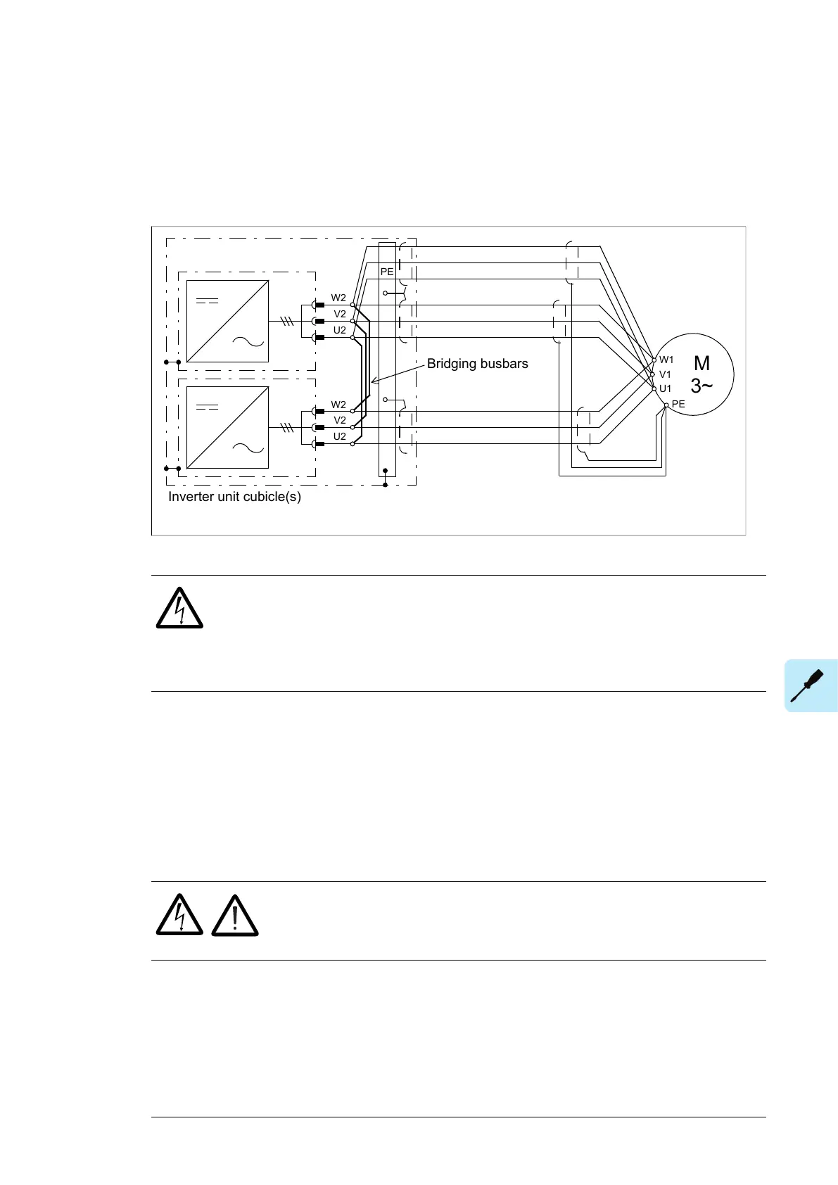
■ Motor connection diagram (with option +H366)
With option +H366, the output busbars of the inverter modules within the same cubicle
are connected by bridging busbars. The bridging balances the motor current between the
modules, which allows more cabling options. For example, it is possible to use a number
of cables that could not otherwise be evenly distributed between the inverter modules.
PE
U2
V2
W2
U2
V2
W2
M
3~
U1
W1
V1
PE
Bridging busbars
Inverter unit cubicle(s)
The recommended cable types are given in chapter Technical data.
WARNING!
The bridging can carry the nominal output of one inverter module. In case of three
parallel modules, ensure that the load capacity of the bridging is not exceeded.
For example, if the cabling connects to the output busbars at one module only,
use the module in the middle.
Note:
The +H366 option only interconnects the outputs of inverter modules within the same cubicle,
not modules installed in different cubicles. Therefore, when the drive has multiple inverter
cubicles (ie. two cubicles of two modules each), make sure that the motor cabling is identical
for both cubicles.
■ Procedure
Refer to the drawings below.
WARNING!
Obey the instructions in chapter Safety instructions. If you ignore them,
injury or death, or damage to the equipment can occur.
1.
Do the steps in section Electrical safety precautions (page 16) before you start the work.
2. Open the inverter module cubicle door.
3. Remove the shrouding at the lower part of the cubicle (not shown).
4. Unplug the wiring from the lower front mounting plate. Remove the plate.
5. Disconnect the wiring from the cooling fans.
6. Undo the two retaining screws (a) of each fan.
Electrical installation 89

 Loading...


