further information, see FDPI-02 diagnostics and panel interface user’s manual
(3AUA0000113618 [English]).
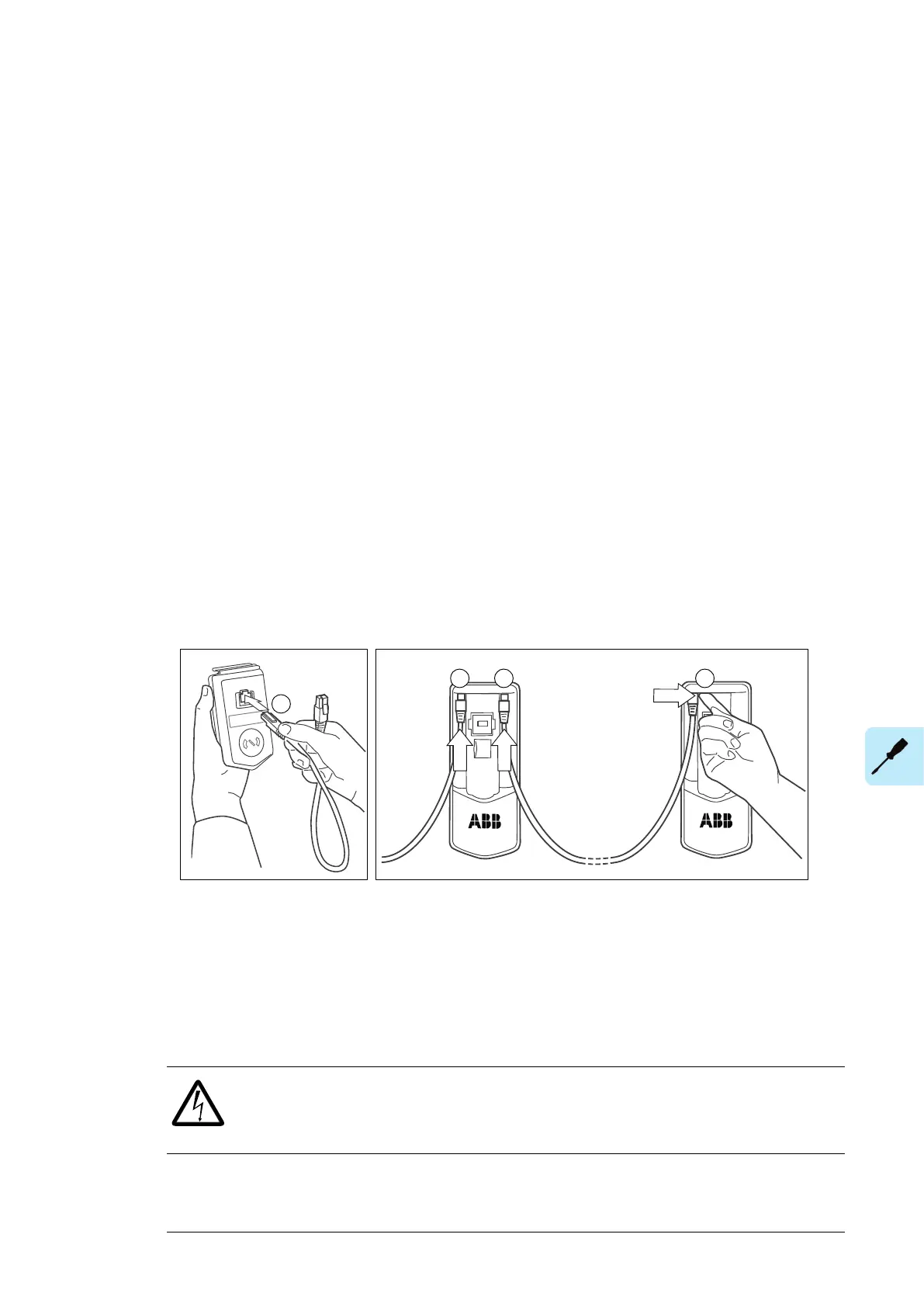
1. Connect the panel to one drive using an Ethernet (eg. CAT5E) cable.
• Use Menu - Settings - Edit texts - Drive to give a descriptive name to the drive
•
Use parameter 49.01 to assign the drive with a unique node ID number
• Set other parameters in group 49 if necessary
•
Use parameter 49.06 to validate any changes.
Repeat the above for each drive.
2. Chain the panel and the drives together using Ethernet cables.
3. Switch on the bus termination on the drive that is farthest from the control panel in the
chain.
• With drives that have the panel mounted on the front cover, move the terminating
switch into the outer position.
• With an FDPI-02 module, move termination switch S2 into the TERMINATED
position.
Make sure that bus termination is off on all other drives.
4. On the control panel, switch on the panel bus functionality (Options - Select drive - Panel
bus). The drive to be controlled can now be selected from the list under Options - Select
drive.
If a PC is connected to the control panel, the drives on the panel bus are automatically
displayed in the Drive composer tool.
Installing option modules
■ Mechanical installation of I/O extension, fieldbus adapter and pulse
encoder interface modules
See hardware description for the available slots for each module. Install the option modules
as follows:
WARNING!
Obey the instructions in chapter Safety instructions. If you ignore them, injury or
death, or damage to the equipment can occur.
1.
Stop the drive and do the steps in section Electrical safety precautions (page 16) before
you start the work.
Electrical installation 101

 Loading...


