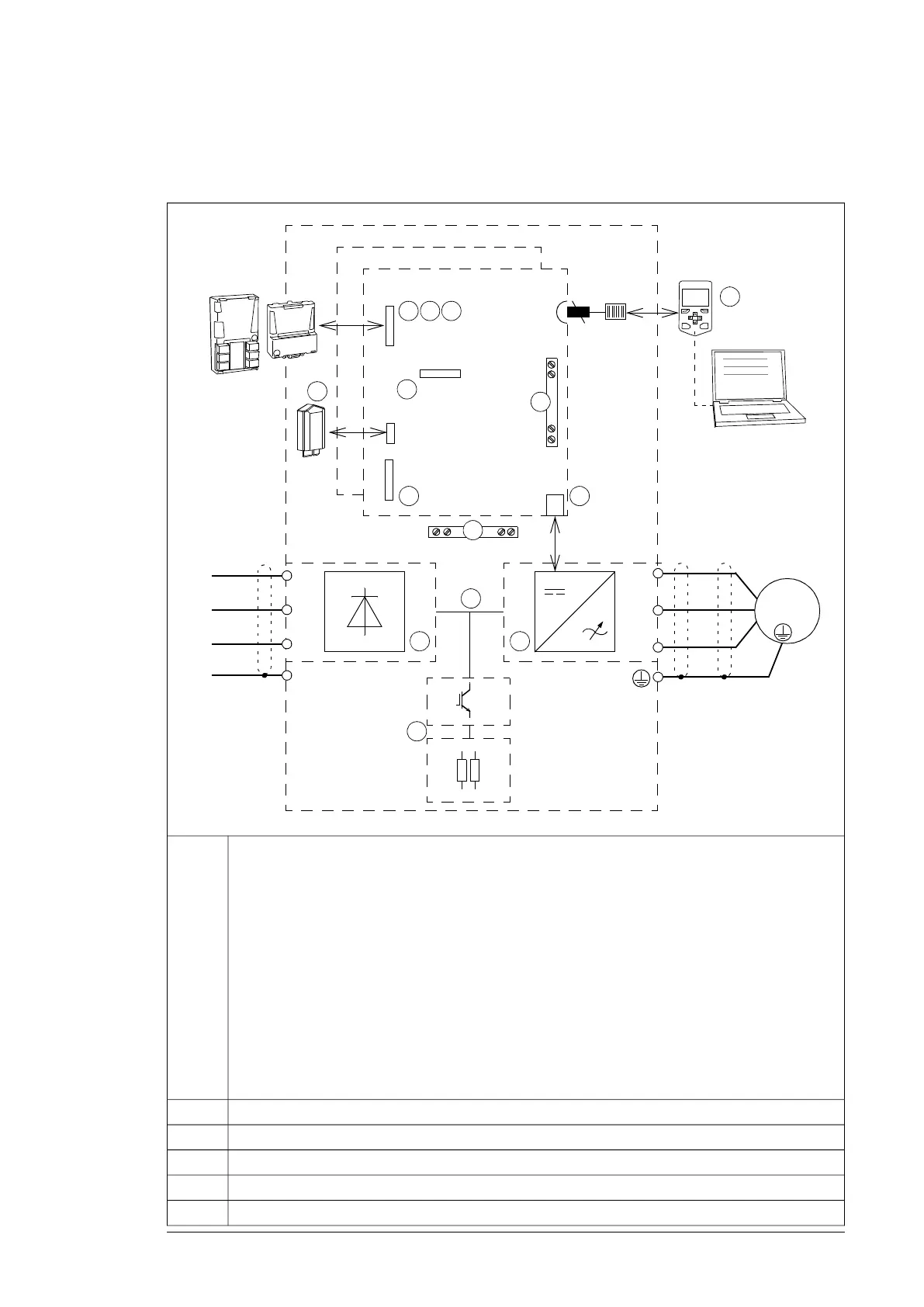
Overview of power and control connections
The diagram shows the power connections and control interfaces of the drive.
L1
L2
L3
PE
U2
V2
W2
M 3 ~
L1
L2
L3
PE
F
x
x
Slots 1, 2 and 3
1
7
..........
..........
..........
..........
.....
.....
6
. . .
. . .
10
..........
..........
4
2 3
Slot 4
5
X205
X12
X13
8
Inverter control unit (A41)
Supply control unit (A51)
V1T/R…
9
11 13
12
14
Drive
F
x
x
x
Option modules can be inserted into slots 1, 2, 3 and 4 as follows:1
SlotsModule type
1, 2, 3Analog and digital I/O extension modules
1, 2, 3Feedback interface modules
1, 2, 3Fieldbus communication modules
4RDCO-xx DDCS communication option module (standard equipment). As standard,
a fiber optic link connects the supply and inverter control units.
2
3
4
Additional modules can be installed on an optional FEA-03 extension adapter connected to an RDCO
module on slot 4.
Memory unit5
Connection for FSO-xx safety functions module (not available at the time of publishing)6
Control panel and PC connection7
Terminal blocks on the inverter control unit.8
Fiber optic link to each inverter module.9
Operation principle and hardware description 37

 Loading...


