Additional markingsOption
Equipment designations and pin identifiers of both ends are marked with snap-on markers (or
equivalent) on conductors that connect to equipment, terminal blocks or detachable plug-type
connectors, or are part of the wiring between power modules. Fiber optic cables are marked
in the same way. Plug-type connector identifications are marked on labels near the connectors.
The label holders are attached around conductor bundles. Main circuit conductors are marked
with white tape or printing. Short and obvious connections are marked with printing (or equi-
valent) only.
+G342
(class C1)
K1 24
K 1 2 4
K1 24
K1 24 T2 3
T 2 3
T2 3
T2 3
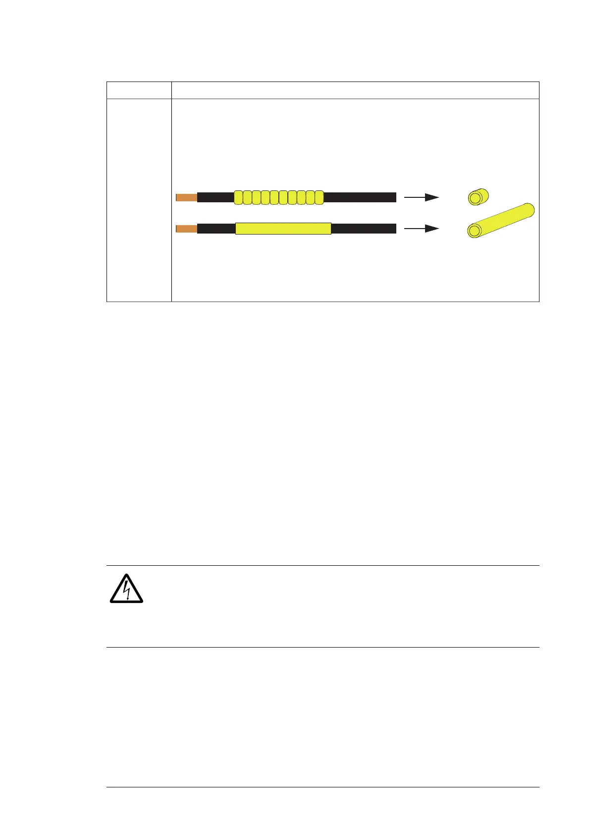
Note:
Even wires with equipment and pin identifiers printed on the wire insulation are marked with
rings or tubing.
■ Cable conduit entry (option +H358)
The option provides US/UK conduit plates (plain 3 mm thick steel plates without any
ready-made holes). US/UK conduit plates are provided as standard with options +C129 and
+C134 instead of the normal cable entries.
■ Common motor terminal cubicle (option +H359)
As standard, each inverter module must be individually cabled to the motor. This option
provides an additional cubicle containing a single set of terminals for the motor cables.
The width of the cubicle and the size of the terminals within depend on the power rating of
the drive.
■ Common output terminal (option +H366)
As standard, each inverter module must be individually cabled to the motor. This option
adds bridging that connects the outputs of multiple (in practice, two or three) inverter modules
mounted in the same cubicle. The bridging balances the motor current between the modules,
which allows more cabling options. For example, it is possible to use a number of cables
that could not otherwise be evenly distributed between the inverter modules.
WARNING!
The bridging can carry the nominal output of one inverter module. In case of three
parallel modules, ensure that the load capacity of the bridging is not exceeded.
For example, if the cabling connects to the output busbars at one module only,
use the module in the middle.
Note:
The +H366 option only interconnects the outputs of inverter modules within the same cubicle,
not modules installed in different cubicles. Therefore, when the drive has more than three
inverter modules, make sure that the load is distributed evenly between the modules:
• In case of two inverter cubicles of two modules, connect the same number of cables to
each cubicle.
• In case of one inverter cubicle with three modules and another with two, each cubicle
requires a number of cables proportional to the number of modules within. For example,
Operation principle and hardware description 43

 Loading...


