Notes:
The wire size accepted by all screw terminals (for both stranded and solid wire) is 0.5 …
2.5 mm
2
(24…12 AWG). The torque is 0.5 N·m (5 lbf·in).
1)
See section Drive-to-drive link (XD2D) (page 111).
2)
See chapter The Safe torque off function (page 189).
3)
0 = Acceleration/deceleration ramps defined by parameters 23.12/23.13 in use. 1 =
Acceleration/deceleration ramps defined by parameters 23.14/23.15 in use.
4)
Constant speed 1 is defined by parameter 22.26.
5)
See section DIIL input (page 111).
6)
Total load capacity of these outputs is 4.8 W (200 mA at 24 V) minus the power taken by
DIO1 and DIO2.
7)
Determines whether DICOM is separated from DIOGND (ie. common reference for digital
inputs floats; in practice, selects whether the digital inputs are used in current sinking or
sourcing mode). See also BCU-x2 ground isolation diagram (page 115). DICOM=DIOGND
ON: DICOM connected to DIOGND. OFF: DICOM and DIOGND separate.
8)
Current [0(4)…20 mA, R
in
= 100 ohm] or voltage [0(2)…10 V, R
in
> 200 kohm] input
selected by switch AI1. Change of setting requires reboot of control unit.
9)
Current [0(4)…20 mA, R
in
= 100 ohm] or voltage [0(2)…10 V, R
in
> 200 kohm] input
selected by switch AI2. Change of setting requires reboot of control unit.
■ External power supply for the control unit (XPOW)
The BCU-x2 is powered from a 24 V DC, 2 A supply through terminal block XPOW. A second
supply can be connected to the same terminal block for redundancy.
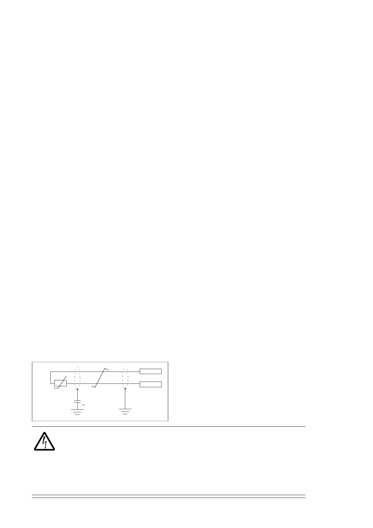
■ DI6 as a PTC sensor input
A PTC sensor can be connected to this input for motor temperature measurement as follows.
The sensor can alternatively be connected to FEN-xx encoder interface module. At the
sensor end of the cable, leave the shields unconnected or ground them indirectly via a
high-frequency capacitor with a few nanofarads, eg. 3.3 nF / 630 V. The shield can also be
grounded directly at both ends if they are in the same ground line with no significant voltage
drop between the end points. See the firmware manual of the inverter unit for parameter
settings.
T
3.3 nF
>
630 V AC
PTC
DI6
+24VD
WARNING!
As the inputs pictured above are not insulated according to IEC 60664, the
connection of the motor temperature sensor requires double or reinforced insulation
between motor live parts and the sensor. If the assembly does not fulfill the
requirement, the I/O board terminals must be protected against contact and must
not be connected to other equipment or the temperature sensor must be isolated
from the I/O terminals.
110 Control units of the drive

 Loading...


