Terminal blocks for customer connections installed in the drive cabinet.10
Supply unit (consisting of one or more supply modules)11
DC intermediate link12
Inverter unit (consisting of one or more inverter modules)13
Optional brake chopper (+D150) and resistors (+D151)14
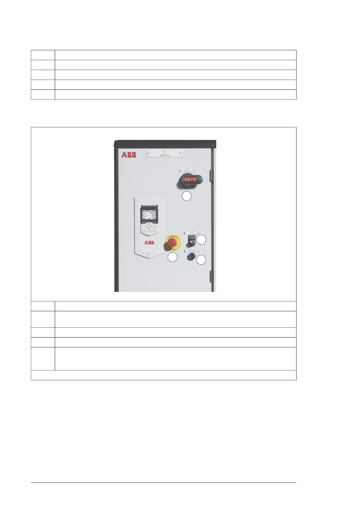
Door switches and lights
DescriptionNo.
Run enable switch for the drive. The switch has to be set to "1" for the drive to start. Turning the
switch into the off position will stop the drive.
1
Emergency stop push button (with emergency stop options only)2
Emergency stop active light and reset (with emergency stop options only)3
Charging switch (with charging circuit option only). At start-up, the charging switch is closed. After
the DC voltage rises to operating level, the supply control unit opens the charging circuit, and the
main supply voltage can be connected to the drive.
4
The layout depends on the options selected.
■ Control panel
The ACS-AP-W is the user interface of the drive. It provides the essential controls such as
Start/Stop/Direction/Reset/Reference, and the parameter settings for the inverter control
program.
38 Operation principle and hardware description

 Loading...


