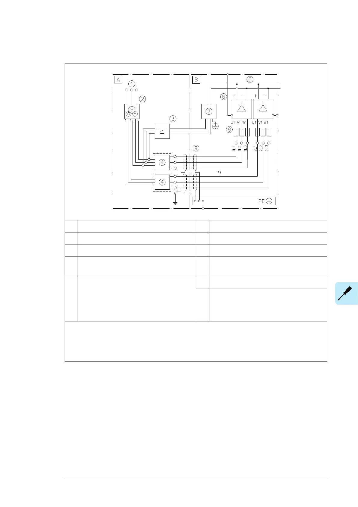
Connection diagram – 2×D8D, 12-pulse, internal charging
Supply unit cubicle of driveBExternal installation outside drive cabinetA
DC link5Medium voltage/low voltage switchboard1
Supply modules6Supply transformer2
Charging circuit (option +F272)7Charging switchgear including:3
• Disconnecting device
AC fuses8Interlocked dedicated supply unit switchgear in-
cluding:
4
360 degrees grounding9
• Disconnecting device
• Breaker/contactor
• Overcurrent and short-circuit protection of input
cabling
Note:
*) Use symmetrical supply cabling to ensure equal current sharing between parallel diode bridges. Required
minimum length of the cables is 5 meters.
For cable and component selection information, see chapter Guidelines for planning the electrical installation.
Electrical installation 95

 Loading...


