5. Twist the cable screens into bundles and connect the bundles to the PE busbar in the
cubicle.
6. Connect any separate ground conductors/cables to the PE busbar in the cubicle.
7. Connect the phase conductors to the output terminals. Use the torques specified under
Tightening torques (page 171).
8. Refit any shrouding removed earlier and close the cubicle doors.
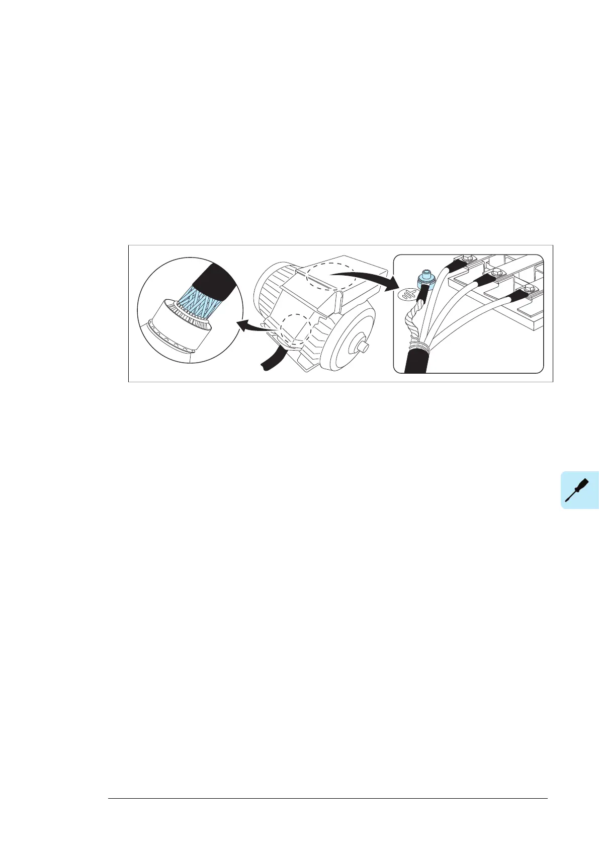
9. At the motor, connect the cables according to instructions from the motor manufacturer.
Pay special attention to the phase order. For minimum radio-frequency interference,
ground the cable shield 360 degrees at the lead-through of the motor terminal box, or
ground the cable by twisting the shield so that the flattened shield is wider than 1/5 of
its length.
Connecting an external brake resistor assembly
See section Electrical installation of custom brake resistors (page 209).
For the location of the terminals, refer to the dimension drawings delivered with the unit or
the dimension drawing examples in chapter .
Electrical installation 93

 Loading...


