Electrical installation of custom brake resistors
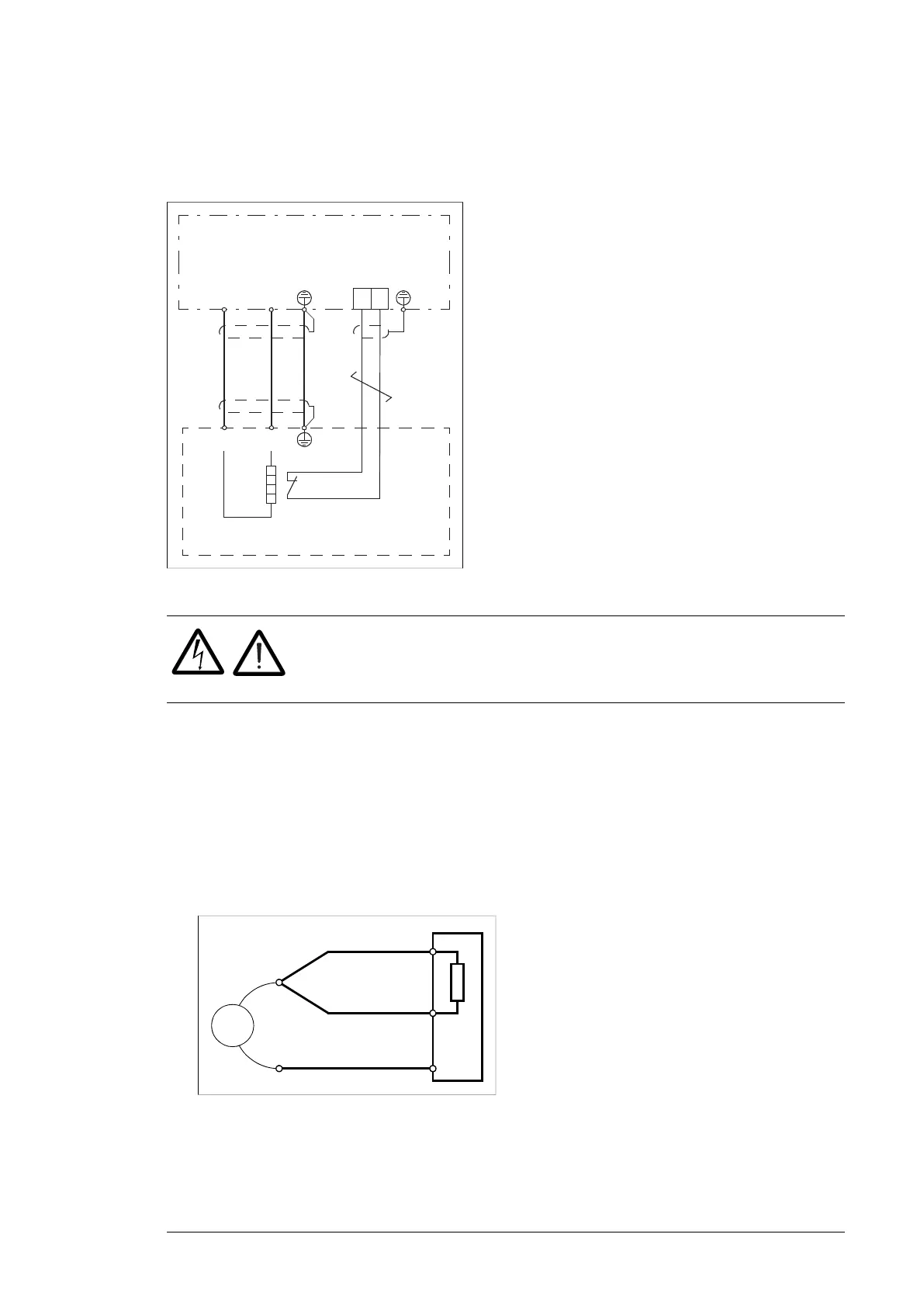
■ Connection diagram
R+ R‚
R+ R‚
123
t°
Brake chopper
Brake resistor
12
X1
■ Connection procedure
WARNING!
Obey the instructions in chapter Safety instructions. If you ignore them,
injury or death, or damage to the equipment can occur.
• Do the steps in section Electrical safety precautions in chapter Safety instructions before
you start the work.
• Connect the resistor cable at the resistor end only. If a shielded three-conductor cable
is used, cut off the third conductor. Ground the twisted shield of the cable as well as
any separate PE conductor (if present).
• At the chopper end of the cable, connect the R+ and R- conductors of the resistor cable
together. Measure the insulation resistance between the combined conductors and the
PE conductor by using a measuring voltage of 1 kV DC. The insulation resistance must
be higher than 1 Mohm.
268 Resistor braking
Connection procedure
WARNING! Obey the instructions in chapter Safety instructions. If you
ignore them, injury or death, or damage to the equipment can occur.
• Do the steps in section Precautions before electrical work on page 19 before you start
the work.
• Connect the resistor cable at the resistor end only. If a shielded three-conductor cable
is used, cut of
f the third conductor. Ground the twisted shield of the cable as well as
any separate PE conductor (if present).
• At the chopper end of the cable, connect the R+ and R- conductors of the resistor
cable together. Measure the insulation resistance between the combined condu
ctors
and
the PE conductor by using a measuring voltage of 1 kV DC. The insu
lation
resistance
must be higher than 1 Mohm.
• Connect the resistor cable to the R+ and R- terminals of the chopper. If a shielded
thre
e-conductor cable is used, cut off the third conductor. Ground the twisted shield
of
the
cable as well as any separate PE conductor (if present).
• Connect the thermal switch of the brake resistor to the enable input (X1) on the brake
chopper
control board. Use cable specified under Thermal protection of the resistors
(page 267). If there are multiple thermal switches, connect them in series.
WARNING! The ENABLE input terminal block of the brake chopper is at
intermediate circuit potential when the supply unit of the drive is running. This
voltage is extremely dangerous and can cause serious damage or injury if the
isolation level and protection conditions for the thermal switches are not sufficient. The
thermal switches must always be properly insulated (over 2.5 kV) and shrouded against
contact.
Start-up
Check the settings of the following inverter control program parameters (ACS880 primary
control program):
• 30.30 Overvoltage control: Overvoltage control disabled.
For settings of other control programs, see the appropriate firmware manual.
Note: New brake resistors may be coated with storage grease. As the brake chopper
operates for the first time, the grease burns off and may produce some smoke. Make sure
there is proper ventilation.
ohm
R-
R+
PE
• Connect the resistor cable to the R+ and R- terminals of the chopper. If a shielded
three-conductor cable is used, cut off the third conductor. Ground the twisted shield of
the cable as well as any separate PE conductor (if present).
Resistor braking 209

 Loading...


