Note for top entry of cables: When each cable has its own rubber grommet, sufficient IP
and EMC protection can be achieved. However, if very many control cables come to one
cabinet, plan the installation beforehand as follows:
1. Make a list of the cables coming to the cabinet.
2. Sort the cables going to the left into one group and the cables going to the right into
another group to avoid unnecessary crossing of cables inside the cabinet.
3. Sort the cables in each group according to size.
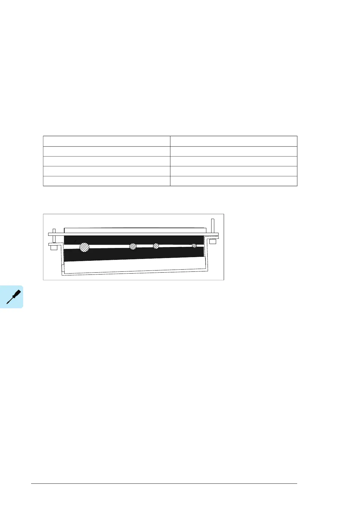
4. Group the cables for each grommet as follows ensuring that each cable has a proper
contact to the cushions on both sides.
Max. number of cables per grommetCable diameter in mm
4≤ 13
3≤ 17
2< 25
1≥ 25
5. Arrange the bunches according to size from thickest to the thinnest between the EMI
conductive cushions.
Electrical installation 99
5. Arrange the bunches according to size from thickest to the thinnest between the EMI
co
nductive cushions.
6. If more than one cable go through a grommet, seal the grommet by applying Lo
ctite
5221 (catalogue number 25551) inside the grommet.
Routing the control cables inside the cabinet
Use the existing trunking in the cabinet wherever possible. Use sleeving if cables are laid
against sharp edges. When running cables to or from the swing-out frame, leave enough
slack at the hinge to allow the frame to open fully.
Connecting to the inverter control unit (A41)
Connect the conductors to the appropriate terminals (see page 127) of the control unit or
terminal block X504 (option +L504).
Connect the inner twisted pair shields and all separate grounding wires to the grounding
clamps below the control unit.
The drawing below represents a drive with additional I/O terminal block (option +L504).
Without the block, the grounding is made the same way.
Notes:
• Do not ground the outer shield of the cable here since it is grounded at the lead-
through.
• Keep any signal wire pairs twisted as close to the terminals as possible. Twisting the
wire
with its return wire reduces disturbances caused by inductive coupling.
6. If more than one cable go through a grommet, seal the grommet by applying Loctite
5221 (catalogue number 25551) inside the grommet.
Routing the control cables inside the cabinet
Use the existing trunking in the cabinet wherever possible. Use sleeving if cables are laid
against sharp edges. When running cables to or from a swing-out frame, leave enough
slack at the hinge to allow the frame to open fully.
Connecting control cabling
Connect the conductors to the appropriate terminals. Refer to the wiring diagrams delivered
with the drive.
With option +L504, the terminals of the inverter control unit are available on terminal block
X504.
Connect the inner twisted pair shields and all separate grounding wires to the grounding
clamps closest to the terminals.
The drawing below represents the grounding of the control cabling when connecting to a
terminal block inside the cabinet. The grounding is done in the same way when connecting
directly to a component such as the control unit.
Notes:
• Do not ground the outer shield of the cable here since it is grounded at the lead-through.
86 Electrical installation

 Loading...


