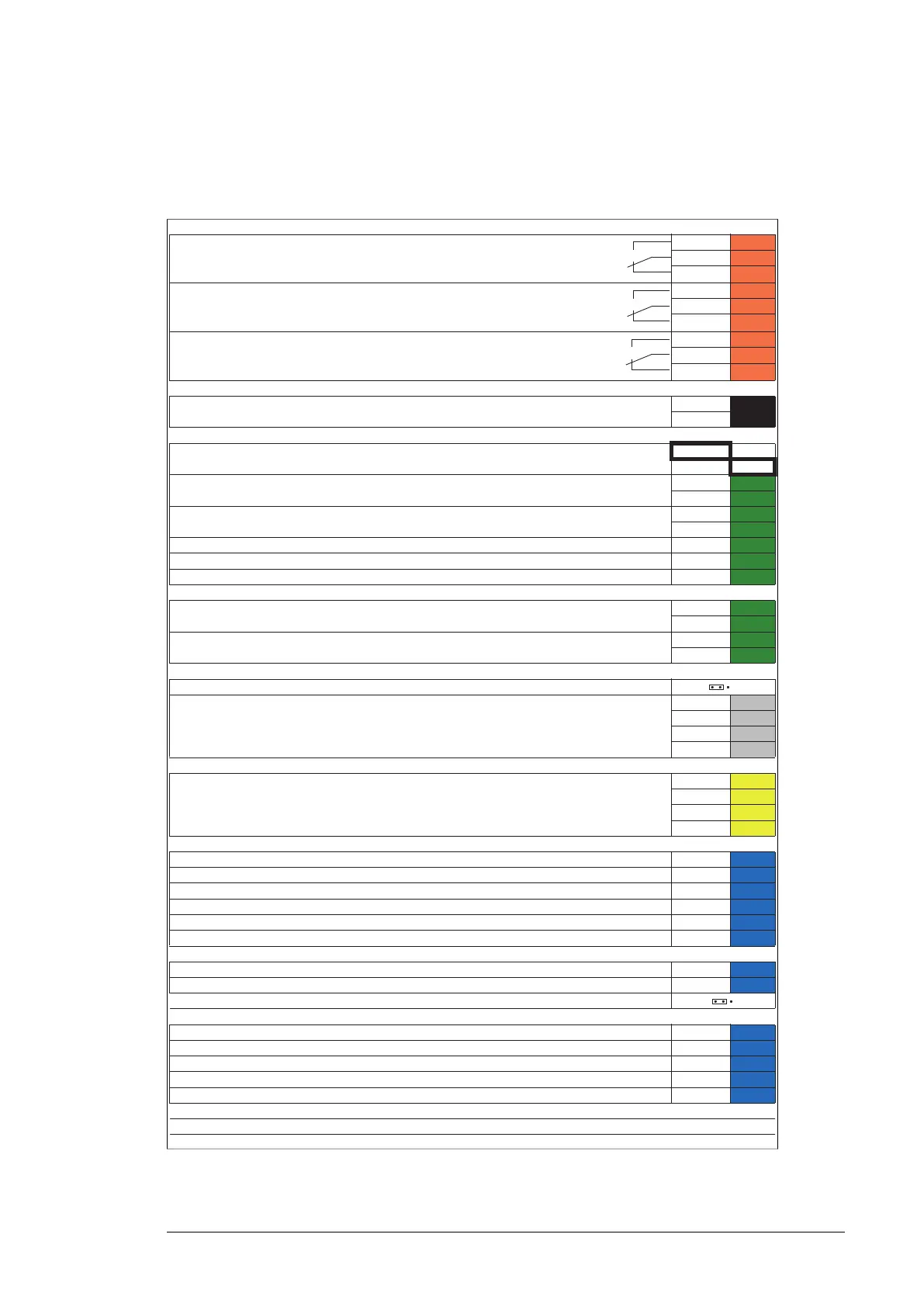
Relay outputs XRO1…XRO3
XRO1: Charging (Charging contactor control)
250 V AC / 30 V DC
2 A
NO
3
COM
2
NC
1
XRO2: Fault(-1)
/ Started
1)
250 V AC / 30 V DC
2 A
NO
3
COM
2
NC
1
XRO3: MCB (Main contactor/breaker control)
250 V AC / 30 V DC
2 A
NO
3
COM
2
NC
1
Power supply XPOW
24 V DC, 2 A
GND
2
+24VI
1
Reference voltage and analog inputs J1, J2, XAI
AI1/AI2 current/voltage selection
AI1: U AI2: U
AI1: I AI2: I
Not in use by default
0(4)…20 mA, R
in
= 100 ohm
2)
AI2- 7
AI2+
6
Not in use by default
0(2)…10 V, R
in
> 200 kohm
3)
AI1- 5
AI1+
4
Ground AGND
3
-10 V DC, R
L
1…10 kohm -VREF 2
10 V DC, R
L
1…10 kohm +VREF 1
Analog outputs XAO
Zero (not in use by default) (0…20 mA, R
L
< 500 ohm)
AGND
4
AO2
3
Zero (not in use by default) (0…20 mA, R
L
< 500 ohm)
AGND
2
AO1 1
Distributed I/O bus J3, XD2D
Termination (ON on units at end of link) ON OFF
Distributed I/O bus for cooling fan monitoring
Shield
4
BGND
3
A
2
B
1
XSTO connector XSTO
For the supply unit to start, both IN1 and IN2 must be connected to OUT.
Note: De-energizing this input will stop the supply unit but will not constitute a true Safe
torque off (STO) function.
IN2
4
IN1
3
SGND
2
OUT
1
Digital inputs XDI
Fault reset (0
ĺ1 = reset) DI6 6
Not in use / Ground fault
4)
DI5 5
Auxiliary circuit breaker fault (0 = tripped) DI4
4
MCB feedback (1 = main breaker/contactor closed) DI3
3
Run enable (1 = Run enable on) DI2
2
Temperature fault (0 = overtemperature) DI1
1
Digital input/outputs XDIO
Input: AC fuse monitoring (0 = tripped) DIO2
2
Not in use / Input: Brake chopper fault (0 = fault)
5)
DIO1 1
Ground selection
6)
Auxiliary voltage output, digital input interlock XD24
Digital input/output ground DIOGND
5
+24 V DC 200 mA
7)
+24VD 4
Digital input ground (common) DICOM
3
+24 V DC 200 mA
7)
+24VD 2
Emergency stop (0 = actuated) DIIL
1
Safety functions module connection (not used) X12
Control panel connection X13
Memory unit connection X205

 Loading...


