Connector data
Connector pitch 5 mm, wire size 2.5 mm
2
Power supply (XPOW)
24 V (±10%) DC, 2 A
External power input. Two supplies can be connected for redundancy.
Connector pitch 5 mm, wire size 2.5 mm
2
Relay outputs RO1…RO3
(XRO1…XRO3)
250 V AC / 30 V DC, 2 A
Protected by varistors
Connector pitch 5 mm, wire size 2.5 mm
2
+24 V output (XD24:2 and XD24:4)
Total load capacity of these outputs is 4.8 W (200 mA / 24 V) minus
the power taken by DIO1 and DIO2.
Connector pitch 5 mm, wire size 2.5 mm
2
Digital inputs DI1…DI6 (XDI:1…XDI:6)
24 V logic levels: “0” < 5 V, “1” > 15 V
R
in
: 2.0 kohm
Input type: NPN/PNP (DI1…DI5), NPN (DI6)
Hardware filtering: 0.04 ms, digital filtering up to 8 ms
DI6 (XDI:6) can alternatively be used as an input for a PTC sensor.
“0” > 4 kohm, “1” < 1.5 kohm.
I
max
: 15 mA (DI1…DI5), 5 mA (DI6)
Connector pitch 5 mm, wire size 2.5 mm
2
Start interlock input DIIL (XDI:7)
24 V logic levels: “0” < 5 V, “1” > 15 V
R
in
: 2.0 kohm
Input type: NPN/PNP
Hardware filtering: 0.04 ms, digital filtering up to 8 ms
Connector pitch 5 mm, wire size 2.5 mm
2
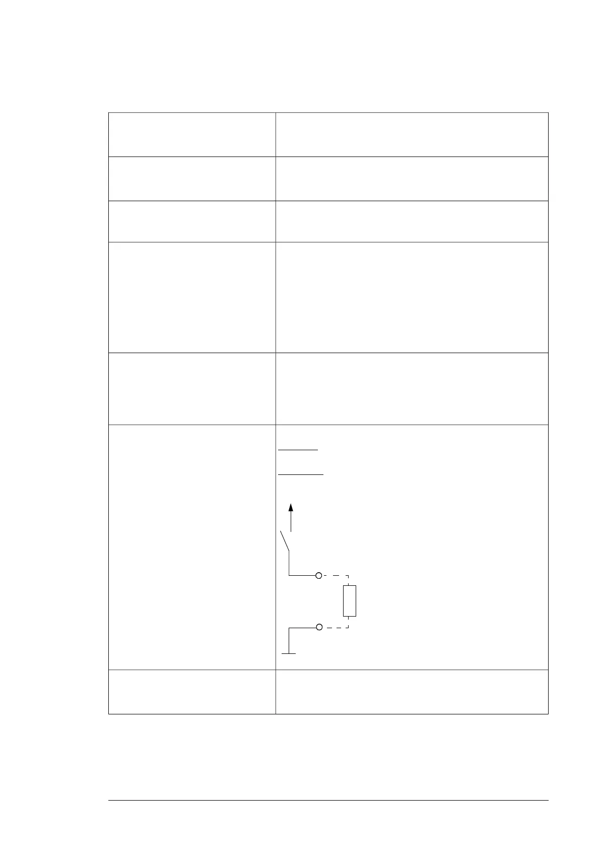
Digital inputs/outputs DIO1 and DIO2
(XDIO:1 and XDIO:2)
As inputs: 24 V logic levels: “0” < 5 V, “1” > 15 V. R
in
: 2.0 kohm. Fil-
tering: 1 ms.
Input/output mode selection by paramet-
ers.
As outputs: Total output current from +24VD is limited to 200 mA
DIO1 can be configured as a frequency
input (0…16 kHz with hardware filtering
of 4 microseconds) for 24 V level square
wave signal (sinusoidal or other wave
form cannot be used). DIO2 can be con-
figured as a 24 V level square wave fre-
quency output. See the firmware manual
of the supply/inverter unit, parameter
group 111/11.
Control units of the drive 135
Control unit connector data
Power supply
(XPOW)
Connector pitch 5 mm, wire size 2.5 mm
2
24 V (±10%) DC, 2 A
External power input. Two supplies can be connected for
redundancy.
Relay outputs RO1…RO3
(XRO1…XRO3)
Connector pitch 5 mm, wire size 2.5 mm
2
250 V AC / 30 V DC, 2 A
Protected by varistors
+24 V output
(XD24:2 and XD24:4)
Connector pitch 5 mm, wire size 2.5 mm
2
Total load capacity of these outputs is 4.8 W (200 mA / 24 V) minus
the power taken by DIO1 and DIO2.
Digital inputs DI1…DI6
(XDI:1…XDI:6)
Connector pitch 5 mm, wire size 2.5 mm
2
24 V logic levels: “0” < 5 V, “1” > 15 V
R
in
: 2.0 kohm
Input type: NPN/PNP (DI1…DI5), NPN (DI6)
Hardware filtering: 0.04 ms, digital filtering up to 8 ms
DI6 (XDI:6) can alternatively be used as an input for a PTC sensor.
“0” > 4 kohm, “1” < 1.5 kohm
I
max
: 15 mA (DI1…DI5), 5 mA (DI6)
Start interlock input DIIL
(XDI:7)
Connector pitch 5 mm, wire size 2.5 mm
2
24 V logic levels: “0” < 5 V, “1” > 15 V
R
in
: 2.0 kohm
Input type: NPN/PNP
Hardware filtering: 0.04 ms, digital filtering up to 8 ms
Digital inputs/outputs DIO1 and DIO2
(XDIO:1 and XDIO:2)
Input/output mode selection by
parameters.
DIO1 can be configured as a frequency
input (0…16 kHz with hardware filtering
of 4 microseconds) for 24 V level square
wave signal (sinusoidal or other wave
form cannot be used). DIO2 can be
configured as a 24 V level square wave
frequency output. See the firmware
manual of the supply/inverter unit,
parameter group 111/11.
Connector pitch 5 mm, wire size 2.5 mm
2
As inputs:
24 V logic levels: “0” < 5 V, “1” > 15 V
R
in
: 2.0 kohm
Filtering: 1 ms
A
s outputs:
Total output current from +24VD is limited to 200 mA
Reference voltage for analog inputs
+VREF and -VREF
(XAI:1 and XAI:2)
Connector pitch 5 mm, wire size 2.5 mm
2
10 V ±1% and –10 V ±1%, R
load
1…10 kohm
Maximum output current: 10 mA
Analog inputs AI1 and AI2
(XAI:4 … XAI:7).
Current/voltage input mode selection by
switches.
Connector pitch 5 mm, wire size 2.5 mm
2
Current input: –20…20 mA, R
in
= 100 ohm
Voltage input: –10…10 V, R
in
> 200 kohm
Differential inputs, common mode range ±30 V
Sampling interval per channel: 0.25 ms
Hardware filtering: 0.25 ms, adjustable digital filtering up to 8 ms
Resolution: 11 bit + sign bit
Inaccuracy: 1% of full scale range
R
L
DIOx
DIOGND
+24VD
Connector pitch 5 mm, wire size 2.5 mm
2
Reference voltage for analog inputs
+VREF and -VREF (XAI:1 and XAI:2)
10 V ±1% and –10 V ±1%, R
load
1…10 kohm
Maximum output current: 10 mA
Control units of the drive 113

 Loading...


