Connecting the motor cables (units without common motor
terminal cubicle)
On units without a common motor terminal cubicle, the motor cables connect to busbars
located in the inverter module cubicles. To access the terminals, the cooling fans and other
equipment in front of the terminals must be removed from the cubicle.
The location and dimensions of the busbars are visible in the dimension drawings delivered
with the drive, as well as the example drawings presented in this manual in chapter
Dimensions.
If the drive is equipped with a common motor terminal cubicle (option +H359), follow the
instructions in section Connecting the motor cables (units with common motor terminal
cubicle) (page 92).
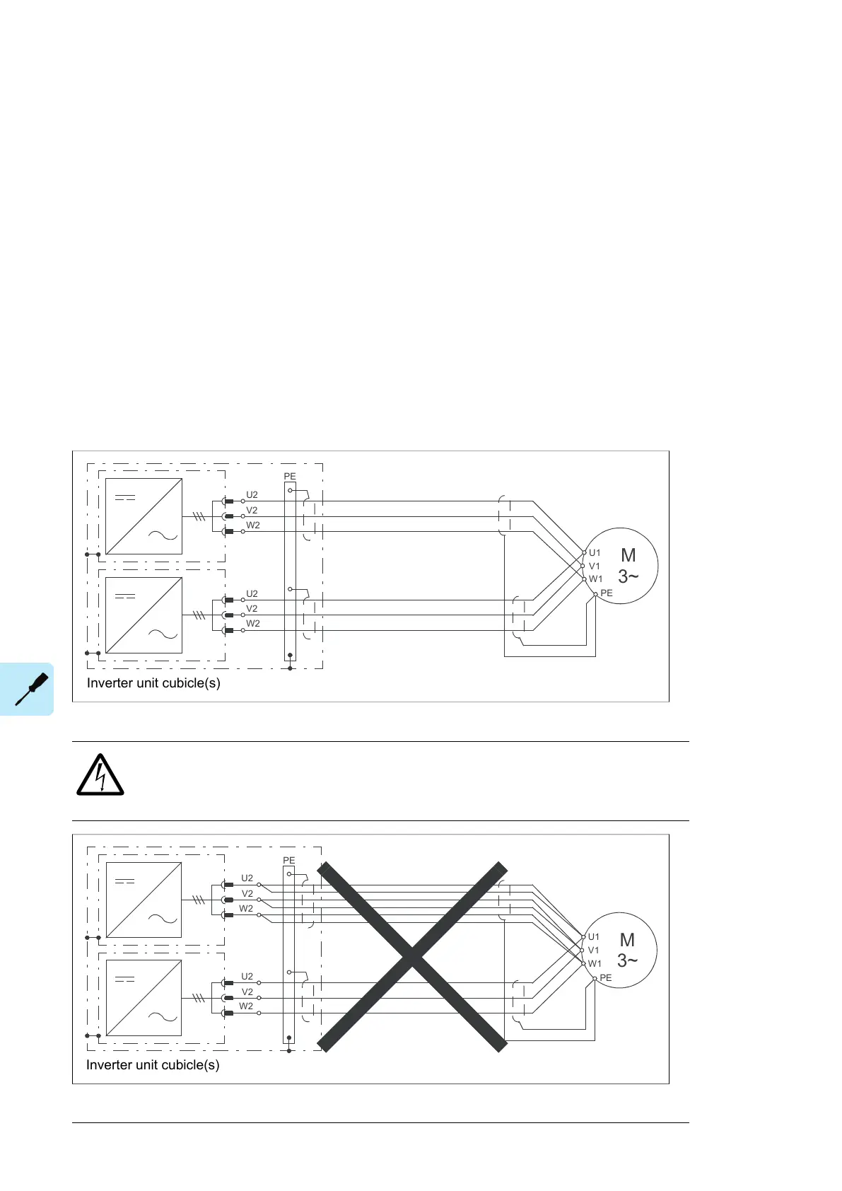
■ Motor connection diagram (without option +H366)
All parallel-connected inverter modules are to be cabled separately to the motor. 360°
earthing is to be used at cable lead-throughs.
U2
V2
W2
PE
U2
V2
W2
M
3~
U1
W1
V1
PE
The recommended cable types are given in chapter Technical data.
WARNING!
The cabling from all inverter modules to the motor must be physically identical
considering cable type, cross-sectional area, and length.
PE
U2
V2
W2
U2
V2
W2
M
3~
U1
W1
V1
PE
88 Electrical installation

 Loading...


