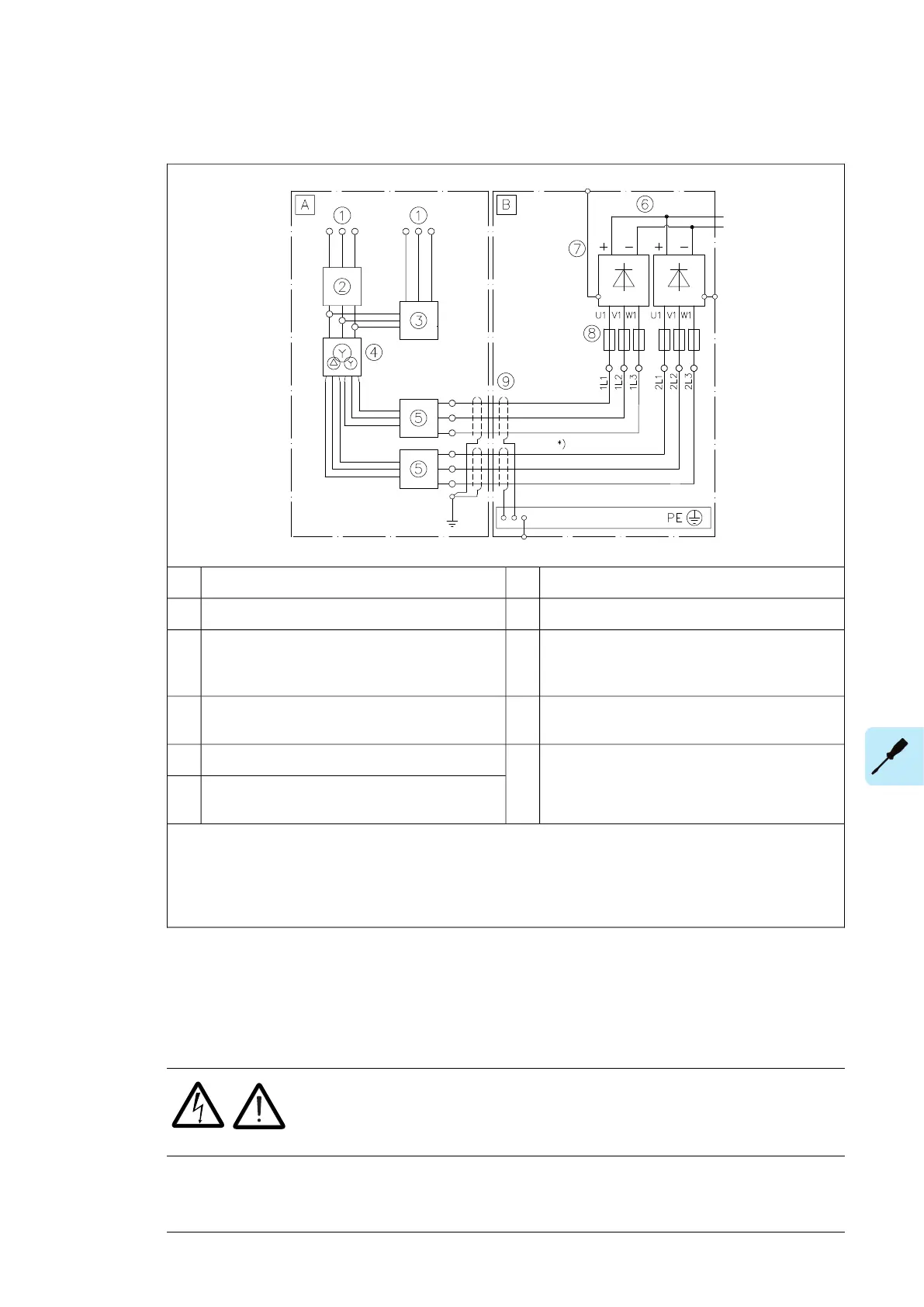
Connection diagram – 2×D8D, 12-pulse, external charging and pre-magnetizing
Supply unit cubicle of driveBExternal installation outside drive cabinetA
DC link6Medium voltage/low voltage switchboard1
Supply modules7Switchgear including:2
• Disconnecting device
• Breaker/contactor
AC fuses8Combined transformer pre-magnetizing circuit
and drive charging circuit
3
360 degrees grounding9Supply transformer4
Overcurrent and short-circuit protection of input
cabling
5
Note:
*) Use symmetrical supply cabling to ensure equal current sharing between parallel diode bridges. Required
minimum length of the cables is 5 meters.
For cable and component selection information, see chapter Guidelines for planning the electrical installation.
■ Layout of the input cable connection terminals and cable entries
The location and dimensions of the busbars are visible in the dimensional drawings delivered
with the drive. Alternatively, see the example dimension drawings in the manual.
■ Connection procedure
WARNING!
Obey the instructions in chapter Safety instructions. If you ignore them,
injury or death, or damage to the equipment can occur.
1.
Do the steps in section Electrical safety precautions (page 16) before you start the work.
2. Open the door of the incoming cubicle.
Electrical installation 97

 Loading...


