To effectively suppress radiated and conducted radio-frequency emissions, the cable shield
conductivity must be at least 1/10 of the phase conductor conductivity. The requirements
are easily met with a copper or aluminum shield. The minimum requirement of the motor
cable shield of the drive is shown below. It consists of a concentric layer of copper wires
with an open helix of copper tape or copper wire. The better and tighter the shield, the lower
the emission level and bearing currents.
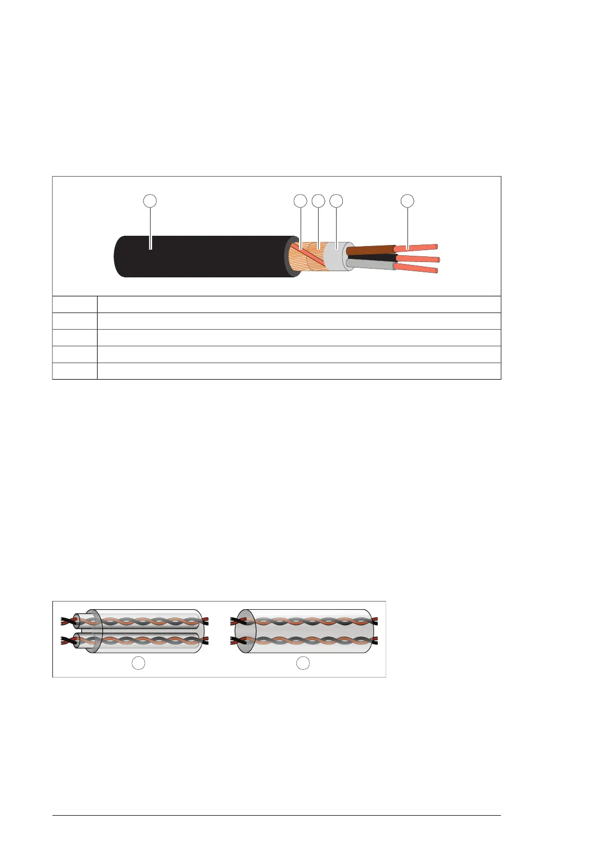
Insulation jacket1
Helix of copper tape or copper wire2
Copper wire screen3
Inner insulation4
Cable core5
Planning the resistor braking system
See chapter Resistor braking (page 203).
Selecting the control cables
■ Shielding
All control cables must be shielded.
Use a double-shielded twisted pair cable for analog signals. This type of cable is
recommended for the pulse encoder signals also. Employ one individually shielded pair for
each signal. Do not use common return for different analog signals.
A double-shielded cable (figure a below) is the best alternative for low-voltage digital signals
but single-shielded (b) twisted pair cable is also acceptable.
■ Signals in separate cables
Run analog and digital signals in separate, shielded cables. Never mix 24 V DC and 115/230
V AC signals in the same cable.
■ Signals allowed to be run in the same cable
Relay-controlled signals, providing their voltage does not exceed 48 V, can be run in the
same cables as digital input signals. The relay-controlled signals should be run as twisted
pairs.
74 Guidelines for planning the electrical installation

 Loading...


