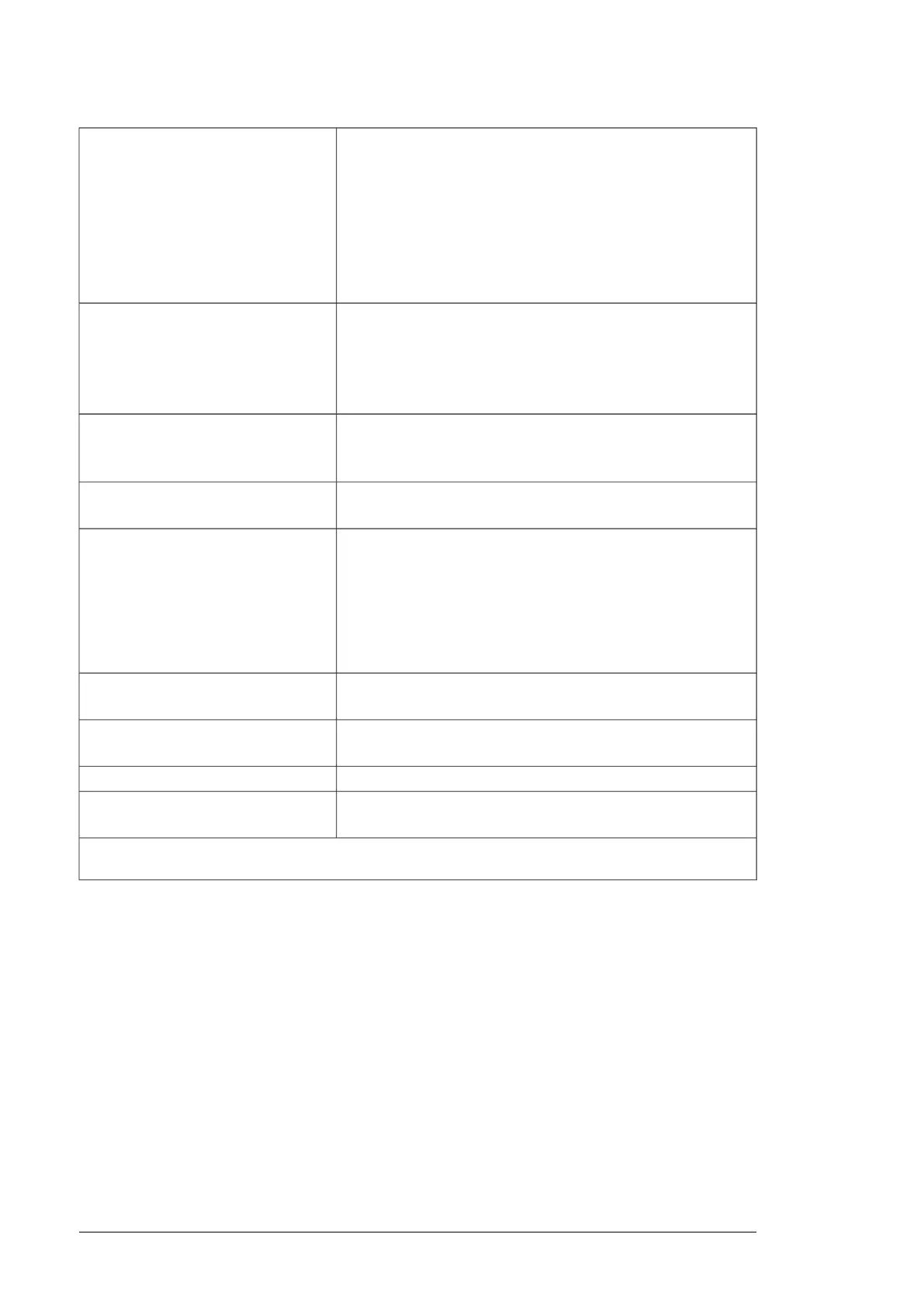
Connector pitch 5 mm, wire size 2.5 mm
2
Analog inputs AI1 and AI2
(XAI:4 … XAI:7).
Current input: –20…20 mA, R
in
= 100 ohm
Current/voltage input mode selection by
switches.
Voltage input: –10…10 V, R
in
> 200 kohm
Differential inputs, common mode range ±30 V
Sampling interval per channel: 0.25 ms
Hardware filtering: 0.25 ms, adjustable digital filtering up to 8 ms
Resolution: 11 bit + sign bit
Inaccuracy: 1% of full scale range
Connector pitch 5 mm, wire size 2.5 mm
2
Analog outputs AO1 and AO2 (XAO)
0…20 mA, R
load
< 500 ohm
Frequency range: 0…500 Hz
Resolution: 11 bit + sign bit
Inaccuracy: 2% of full scale range
Connector pitch 5 mm, wire size 2.5 mm
2
Drive-to-drive link (XD2D)
Physical layer: RS-485
Termination by jumper or switch
Connector pitch 5 mm, wire size 2.5 mm
2
RS-485 connection (X485)
Physical layer: RS-485
Connector pitch 5 mm, wire size 2.5 mm
2
Safe torque off connection (XSTO)
Input voltage range: -3…30 V DC
Logic levels: “0” < 5 V, “1” > 17 V. For the unit to start, both connec-
tions must be “1”.
Current consumption: 66 mA (continuous) per STO channel per R8i
inverter module
EMC (immunity) according to IEC 61326-3-1
Connector pitch 5 mm, wire size 2.5 mm
2
Safe torque off output (XSTO OUT)
To STO connector of inverter module.
Connector: RJ-45Control panel connection (X13)
Cable length < 3 m
Connector: RJ-45Ethernet connection (XETH)
Memory card type: SDHCSDHC memory card slot (SD CARD)
Maximum memory size: 4 GB
The terminals of the control unit fulfill the Protective Extra Low Voltage (PELV) requirements. The PELV re-
quirements of a relay output are not fulfilled if a voltage higher than 48 V is connected to the relay output.
114 Control units of the drive

 Loading...


