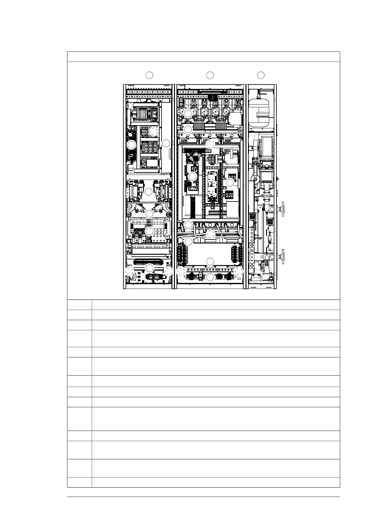
Frame 3×D8D + 3×R8i
A B C
1
2
3
4
5
6
7
8 9 8 9
7
7
10
11
12
1
13
14
15
16
DescriptionNo.
Supply module cubicleA
Inverter module cubicleB
Optional liquid cooling unit. See ACS880-1007LC liquid cooling unit user's manual (3AXD50000129607
[English]).
C
Swing-out frame for installation of control equipment. The frame is hinged and can be turned aside.1
(Behind the swing-out frame) Fan and air-to-liquid heat exchanger. The fan forces air inside the cubicle
through the heat exchanger. See chapter Internal cooling circuit (page 143).
2
ZCU-14 supply control unit. See chapter Control units of the drive (page 103).
3
Frame D8D supply modules4
AC fuses5
Input terminals. Each supply module has its own input terminals, and must be cabled individually
and identically from the supply switchgear. The input cables must be at least 5 meters (16.4 ft) in
length.
6
Mounting plates with terminal blocks for customer connections and space for auxiliary equipment7
(Behind the mounting plate) Inlet manifold with stop and drain valve. See chapter Internal cooling
circuit (page 143).
8
(Behind the mounting plate) Outlet manifold with stop and drain valve. See chapter Internal cooling
circuit (page 143).
9
DC fuses10
Operation principle and hardware description 35

 Loading...


