Advant
®
Controller 450 User’s Guide
Chapter 2 Installation
2-22 3BSE 002 415R701 Rev A
CE-marked Design
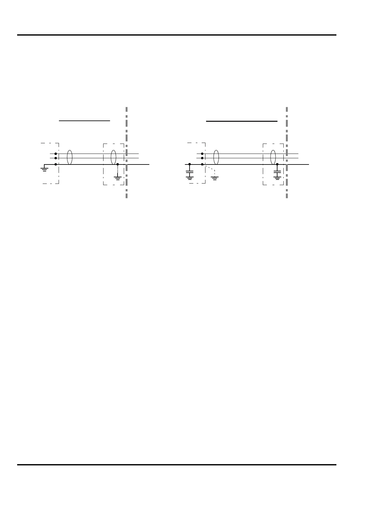
I addition to the general instruction found above, further interference suppression of the cable
shield is made at the enclosure port by individual methods adapted to the different types of
communication. The schematic principles of direct grounding and h.f. grounding by a capacitor
are shown in Figure 2-10.
At direct grounding of the communication cable shield, the illustration in Figure 2-9 is
applicable.
The grounding via a capacitor is based on a Capacitive Decoupling Unit, which is mounted on
the horizontal mounting bar. The cable then passes the cabinet bottom unstripped.
See Figure 2-11.
Figure 2-10. Principles of Grounding of Communication Cable Shields in a CE-marked Design
Cabinet
Cabinet
Field
Field
Direct Grounding
Grounding by Capacitor
Modem/
Circuit board/
Connection unit/
Terminal block
Modem/
Circuit board/
Connection unit/
Terminal block
Cable Holder Capacitive
Decoupling
Unit
In one end
only