Advant
®
Controller 450 User’s Guide
Section 2.2.8 Controller
3BSE 002 415R701 Rev A 2-31
2.2.8 Controller
Assembly
All equipment included in the controller is factory assembled. Cabinet arrangement and similar
questions are dealt with in the general setup instructions above.
Electric Installation
Apart from the process I/O connections and communication connections, which are treated
separately, there is little electric installation. Grounding of the cabinet, equipment, cable shields,
and power supply connection are covered in the general setup instructions above. In addition to
that, make the following connections of functions when appropriate:
• Run/Alarm relay
• External clock synchronization
• Additional supervisory inputs.
The location of the connections within the cabinet are specified in the terminal diagram form
enclosed at delivery.
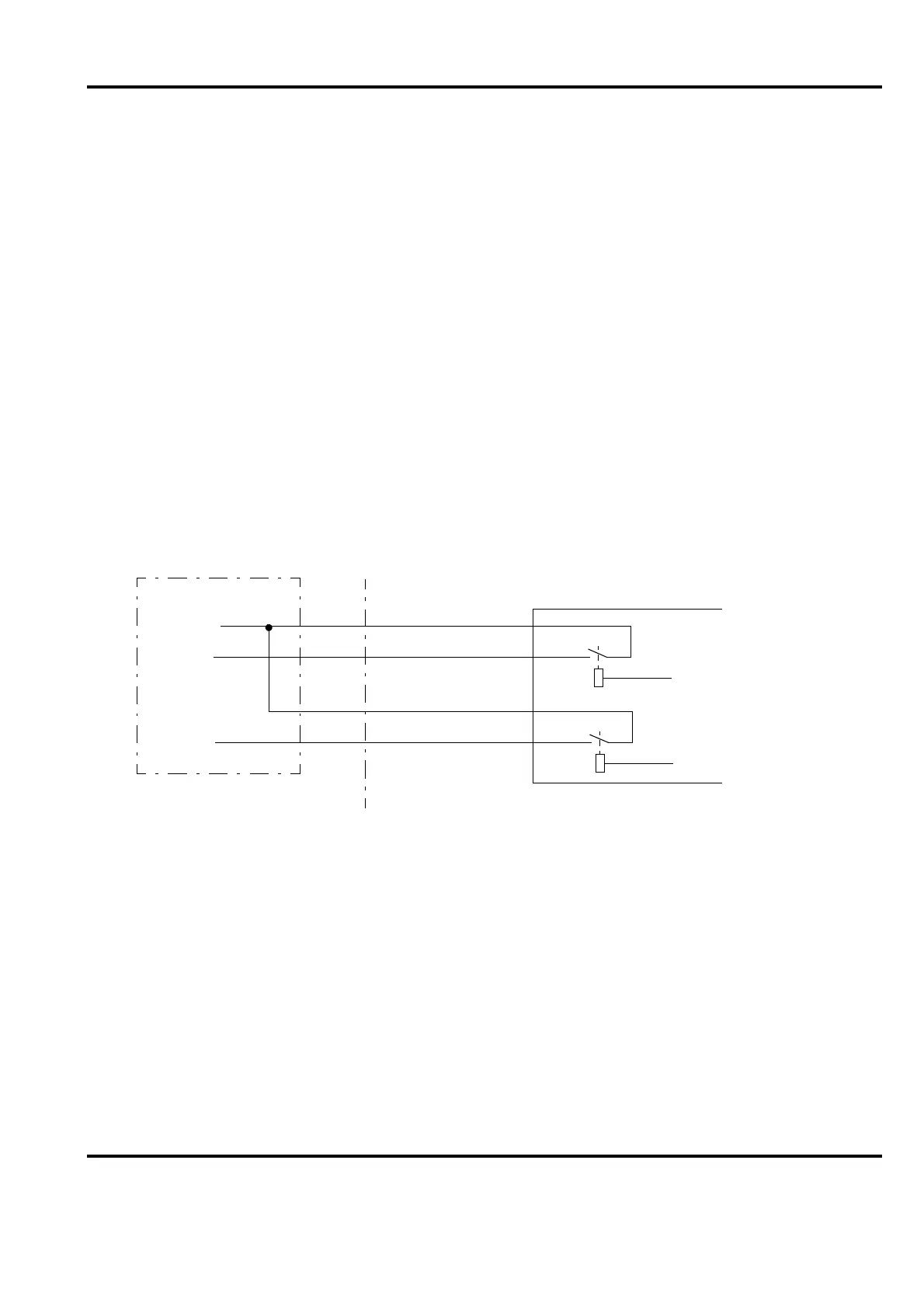
Run/Alarm Relay
Figure 2-17. Connection of Run /Alarm Relay
RUN
7
8
RA
RA
RUN
9
10
RB
RB
Processor
Module A
Processor
Module B
TC520
AC 450
External alarm
announcement
Supply
Ind. A
Ind. B
Configuration: No