Advant
®
Controller 450 User’s Guide
Chapter 2 Installation
2-32 3BSE 002 415R701 Rev A
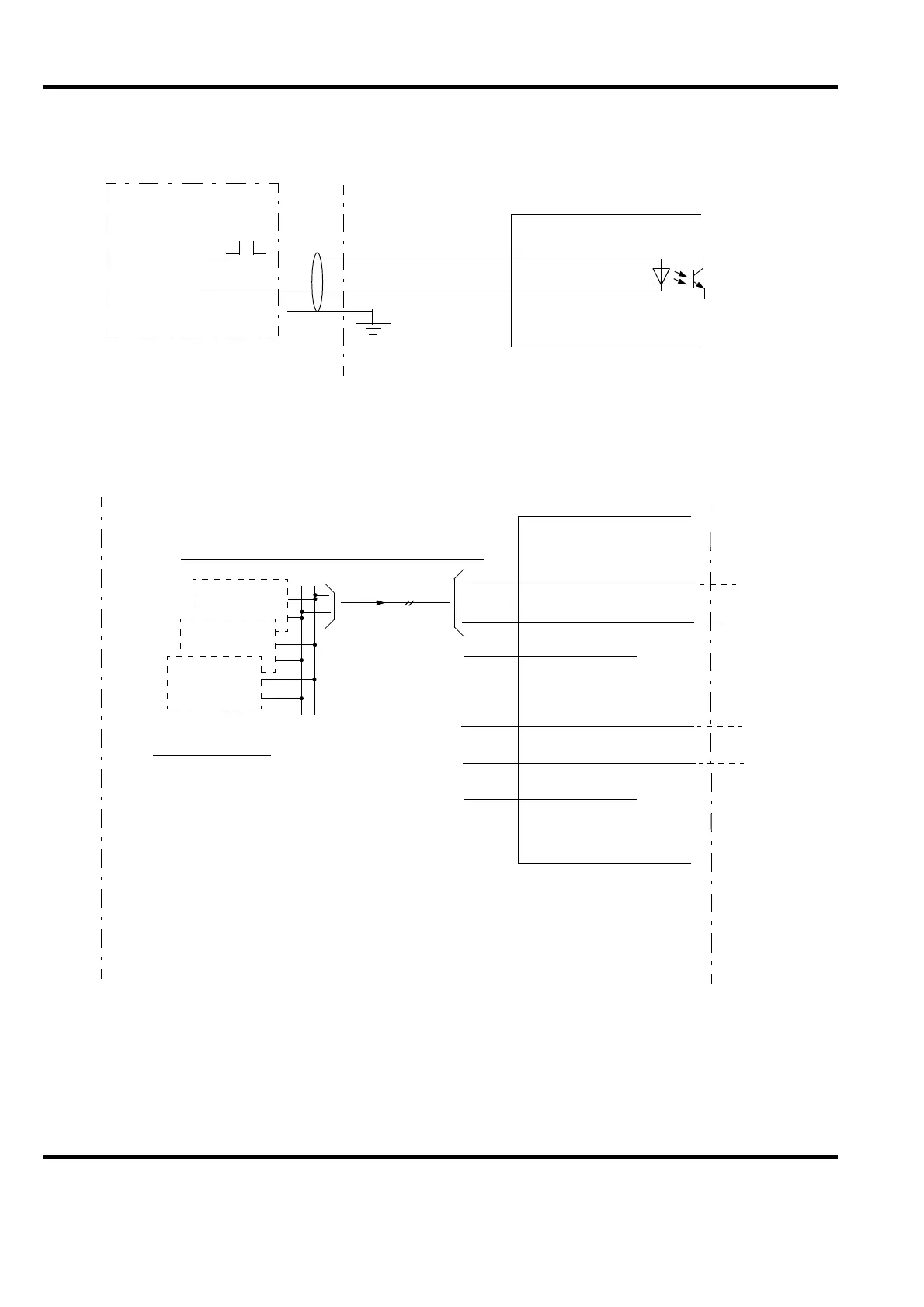
External Clock Synchronization
Additional Supervisory Inputs
Figure 2-18. Connection of External Clock Synchronization
Figure 2-19. Connection of Additional Supervisory Inputs
12
13
SYNCIN
COMM.SYNC
TC520
AC 450
External clock
Description/Configuration: DB element Clock Synch
S
SG
AC 450
TC520
Voting units/Optical S100 bus extension modems
Diagnostics at redundancy
(normally factory installed)
FAIL 24 A
1
2
3
STATUS A1
STATUS A2
COMMON A
System status
display in
operator station
or F1
or F2
4
5
6
STATUS B1
STATUS B2
COMMON B
F3
F4
FAIL 24 B
0V
Description/Configuration:
(I/O) 24VA
(I/O) 24VB
A1
A2
AG
B1
B2
BG
Application notes
.
24 V d.c. inputs (A1, A2, B1, B2)
.
A1, A2
Alternative applic. (configurable):
-
According to figure
Supervision of (I/O) 24 VA, (I/O) 24 VB
Error state = 24 V
-
Free disposition
Supervision of F1, F2
Error state = 0 V or disconnection
.
B1, B2 Free disposition
Supervision of F3, F4
Error state = 0 V or disconnection
.
Signal cables may not be extended outside the
controller cabinets due to the risk of interference
DB element AC 450