$GYDQW
&RQWUROOHU8VHU¶V*XLGH
&KDSWHU &RQILJXUDWLRQ$SS OLFDWLRQ%XLOGLQJ
3-8 3BSE 002 415R701 Rev A
With respect to the actual power supply distribution within the Advant Controller installation
and planned distribution board fusing, please use the figures in Table 3-4 to calculate a suitable
distribution board fusing.
The fuse dimensioning current in the table is settled with respect to:
• lowest supply voltage (19 V/38 V for 24 V and 48 V d.c. systems, respectively)
• efficiency factor of the power supply unit SD150 (ca 0.75)
• margin (1.25 x calculated load current).
The minimum fuse rating is determined by the miniature circuit breakers in the actual power
switch and distribution units.
At 24 V d.c., the minimum value is normally 50 A. At 48 V d.c., the minimum value is 25 A.
)XVH'LPHQVLRQLQJ&XUUHQW)'&
General:
FDC = Load effect ⋅ 1/Efficiency factor ⋅ 1/Lowest supply voltage ⋅ Margin
At 24 V d.c mains supply:
FDC = Load effect ⋅ 1/0.7 ⋅ 1/19 ⋅ 1.25
At 48 V d.c. mains supply:
FDC = Load effect ⋅ 1/0.7 ⋅ 1/38 ⋅ 1.25
In addition, these formulas are also applicable when a detailed current consumption (and thus
the load effect) for a subrack is available and when it should be transformed into fuse
dimensioning current. The figures in Table 3-4 are almost “worst case.”
The in-rush current at redundant power supply units SD150 connected to the same line is
normally no problem and consequently, you should not consider it when dimensioning the
distribution board fusing. In continuous operation, they will share the load.
A more practical installation of redundancy uses duplicated line voltages. Then identical fusing
according to the above table and rules are realized.
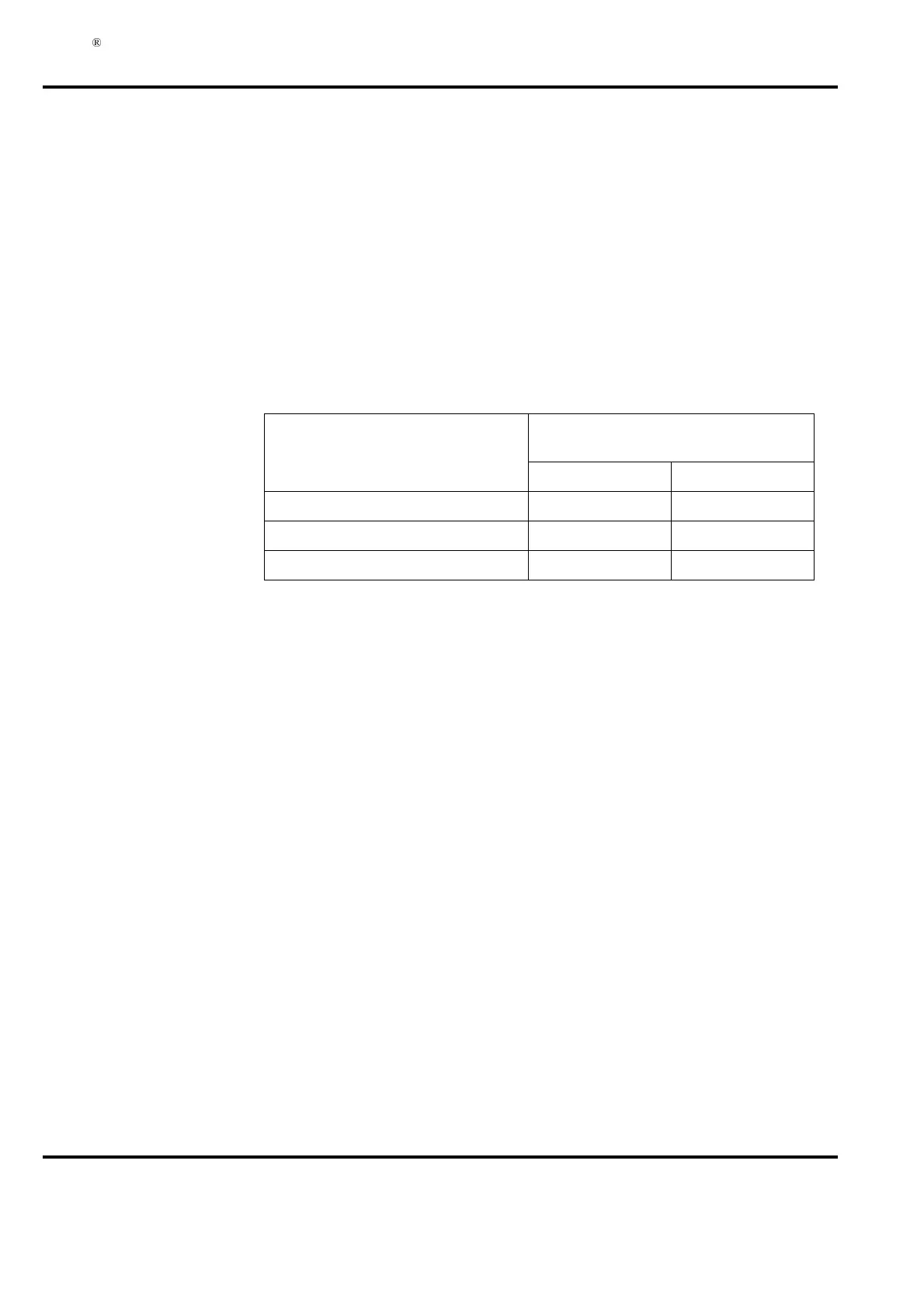
7DEOH 'DWDWR6HWWOHWKH'LVWULEXWLRQ%RDUG)XVLQJGF
,WHP
)XVH'LPHQVLRQLQJ&XUUHQW
5HFRPPHQGHG
9GF 9GF
Controller subrack 19 A 9.5 A
I/O subrack 18 A 9 A
Field equipment
(1)
(1) If a power supply unit for field equipment, type SD150, is included, please use a formula to
calculate the Fuse Dimensioning Current.
(1)